
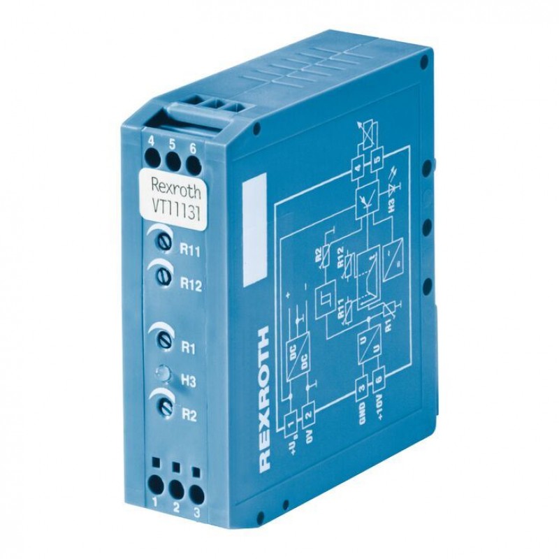
Доступно к заказу
Цена по запросу
И выбери подходящего.
Description
- Component series 1X
- Analog, Modular design
- For valves:
(Z)DBE 6-1X
DBE(M) 10-3X, DBE(M) 10-5X
DBE(M) 20-3X, DBE(M) 20-5X
ZDRE 10-1X
Features
- Differential input for voltage
- Ramp generator with separately adjustable ramp times "up/down"
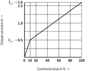
- Maximum current and 10% current adjustable
- Characteristic curve generator
- Clocked power output stage
- LED display of the solenoid control (brightness proportional to the solenoid current)
- Reverse polarity protection for the operating voltage
Product description
The amplifier modules are suitable for the control of a proportional solenoid. They are snapped onto top hat rails according to EN 60715. The electrical connection is established via screw terminals. The modules are operated at 24 V direct voltage.
The solenoid current (actual value) is measured and compared to the externally provided command value. Any occurring differences between actual value and command value, e. g. caused by a change of the solenoid temperature or the operating voltage, are compensated.
The activation of the solenoid control is indicated by LED “H3”; its brightness is proportional to the solenoid current.
Using one trimming potentiometer each, the following can be set from the outside:
a separate ramp time for upwards and downwards ramp (via R11, R12 → tmax approx. 5 s)
the incline of the output characteristic curve (via R1, R2)
Type code
| 01 | Valve amplifier for proportional valves without electrical position feedback, Analog, Modular design For valves: |
| 02 | Component series 10 ... 19 (10 ... 19: unchanged installation and connection dimensions) |
| 03 | Further details in the plain text |
| 01 | 02 | 03 | ||
| VT 11131 | ‒ | 1X | / | * |
Technical data
General
| Component series | 1X | |
| Type of electronics | Analog | |
| Design | Modul |
Voltage supply
| Operating voltage | Nominal | U | V | 24 |
| Lower limit value | UB(t)min | V | 21 | |
| Upper limit value | UB(t)max | V | 35 | |
| Power consumption | max. | Smax | VA | 28 |
| Current consumption | max. | Imax | A | 1.3 |
| Fuse | Electronic short-circuit monitoring of the solenoid | |||
Analog inputs
| Command value | Voltage (differential input) | U | V | 0 ... 10 | |
| Voltage (differential input) | Input resistance | R | kΩ | ≥ 10 | |
Solenoid outputs
| Solenoid current | max. | Imax | A | 1.6 |
| Coil resistance at 20°C | R(20) | Ω | 5.4 | |
| Clock frequency | Factory setting | f | Hz | 300 ±15 % |
Adjustment options
| Solenoid current | % | I10% to Imax | |
| Ramp time up/down | t | s | 0.05 … 5 |
| I10 % | Pre-set to 0.5 A |
Displays
| LED display | Solenoid current | Brightness is proportional to the solenoid current |
Supplementary information
| Anschlussart | 6 screw terminals | ||
| Mounting type | Top hat rail TH 35-7.5 according to EN 60715 | ||
| Type of protection according to EN 60529 | IP 20 | ||
| Ambient temperature range | ϑ | °C | 0 … 50 |
| Storage temperature range | ϑ | °C | -25 … 85 |
| Weight | m | kg | 0.13 |
(For applications outside these values, please consult us!)
Notice:
Information on the environment simulation testing for the climate area, see data sheet 30309-U.
Diagrams/characteristic curves
Output characteristic curve
Operating and display elements
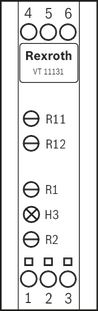
| Factory setting | ||
| R1 | Imax | 1.6 A |
| R2 | I10 % | 0.5 A |
| R11 | Ramp time "Ramp up" | min. |
| R12 | Ramp time "Ramp down" | min. |
| H3 | Solenoid current |
Symbols/Circuit diagrams
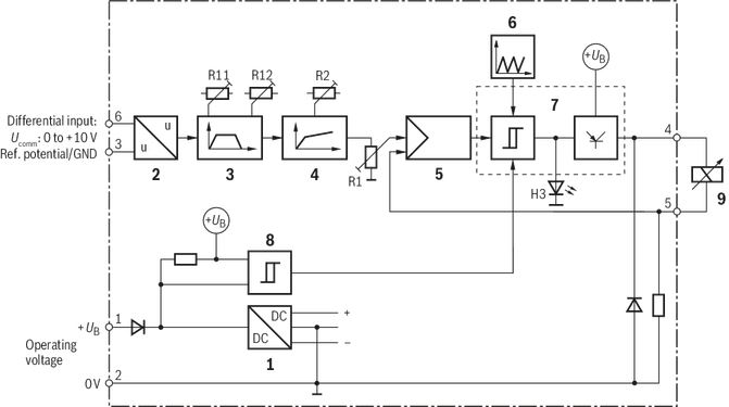
| Power supply unit | |
| Differential amplifier | |
| Ramp generator | |
| Characteristic curve generator | |
| Current controller | |
| Clock generator | |
| Power output stage | |
| Switching stage | |
| Proportional solenoid |
Dimensions
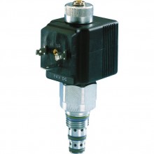
Mounting cavity R/T-8A; 2 main ports; thread M16 x 1.5 mm
Dimensions in mm
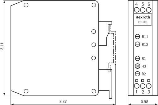
Dimensions in mm
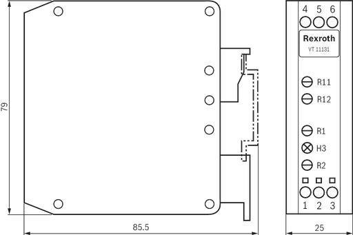
Project planning information
The amplifier module may only be wired when de-energized.
The distance to aerial lines, radios, and radar systems has to be at least 1 m.
Shield command value lines, do not install them close to power cables; shield solenoid conductors.
Do not use free-wheeling diodes in the solenoid conductors.
With a strongly fluctuating operating voltage, it may in individual cases be necessary to use an external smoothing capacitor with a capacity of at least 2200 µF. Recommendation: VT 11110 capacitor module; sufficient for up to 3 amplifier modules.
Downloads


Нет отзывов об этом товаре.