
Артикул: RX7371
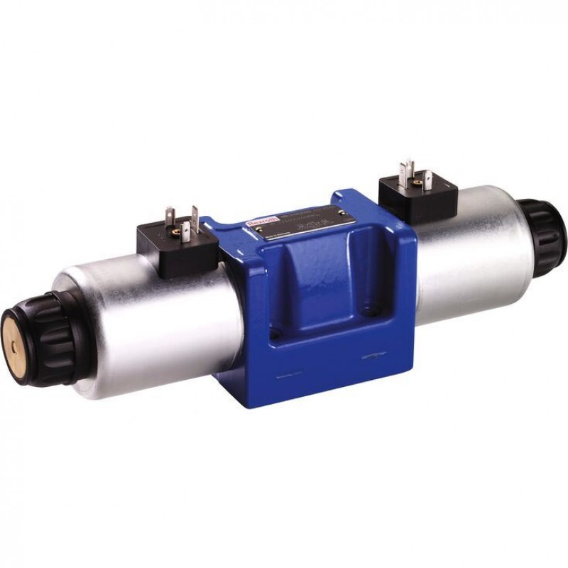
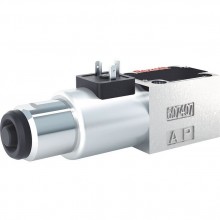
Directional spool valves, direct operated, with solenoid actuation 5-.WE
Доступно к заказу
Цена по запросу
И выбери подходящего.
Description
- 5-chamber version
- Size 10
- Component series 5X
- Maximum operating pressure 420 bar
- Maximum flow 150 l/min
Features
- 4/3-, 4/2- or 3/2-way version
- Porting pattern according to ISO 4401-05-04-0-05
- High-power solenoid, optionally rotatable by 90°
- Electrical connection as individual connection
- Use optionally with PWM connector (fast switching amplifier, energy reduction)
- Optional auxiliary operating device
- Spool position monitoring, optional
- CE conformity according to the Low-Voltage Directive 2006/95/EC for electrical voltages >50 VAC or > 75VDC
- Solenoid coil with UR approval UL 429
- Approval according to CSA C22.2 no. 139-10, optional
Product description
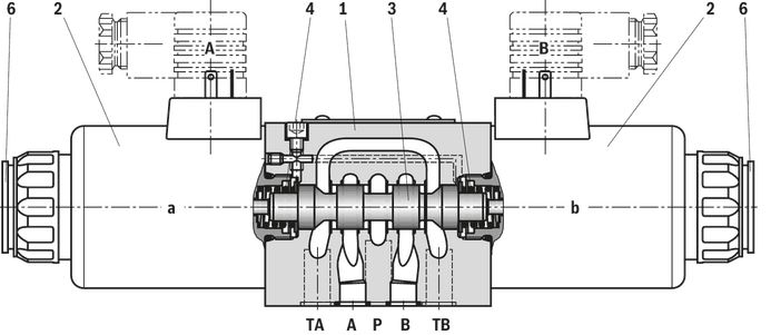
The 5-chamber directional valve type 5-.WE is a solenoid-actuated directional spool valve with switching time increase. It controls the start, stop and direction of a flow. The directional valve basically consists of housing (1), one or two electronic solenoids (2), control spool (3), and the return springs (4).
In de-energized condition, the control spool (3) is held in the central position or in the initial position by the return springs (4) (except for valves without spring "O").
If the wet-pin electronic solenoid (2) is energized, the control spool (3) moves out of its rest position into the required end position. In this way, the required direction of flow according to the selected symbol is released.
After the electronic solenoid (2) has been switched off, the control spool (3) is pushed back into the central position or in the initial position (except for valve with "OF" detent and valve without spring type "O").
A manual override (6) allows for the manual switching of the valve without solenoid energization.
To ensure proper functioning, make sure that the pressure chamber of the solenoid is filled with oil.
Type 5-4WE 10 …
Throttle insert
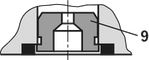
Using a throttle insert (9) in channels P, A, B or T, the flow resistance at the valve can be increased. Its use is required when, due to prevailing operating conditions, flows occur during the switching processes, which exceed the performance limit of the valve.
Without spring return “O” (only possible with symbols A, C and D)
This version is a directional valve with 2 spool positions and 2 electronic solenoids without detent. The valve without spring return at the control spool (3) does not have a defined basic position in the de-energized condition.
Without spring return with detent “OF” (only possible with symbols A, C and D)
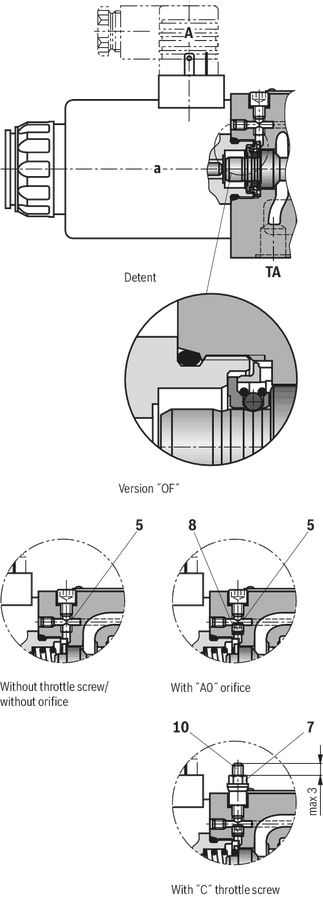
This version is a directional valve with 2 spool positions and 2 electronic solenoids with detent. The detents are used to lock the control spool (3) in the relevant spool position. During operation, continuous application of current to the electronic solenoid can thus be omitted which contributes to energy-efficient operation.
Notice:
Pressure peaks in the tank line to two or several valves can result in unintended movements of the control spool in the case of valves with detent. We therefore recommend that separate return lines be provided or a check valve installed in the tank line.
Influencing the switching time
With the 5-chamber directional valve type 5-.WE, the switching time can be delayed to 100 ms and more by means of a throttle screw "C" (7) or a selected orifice "A0.” (8). In this connection, the switching time is pressure-, flow- and viscosity-dependent, specific to the installation. The switching time is influenced by means of a restriction (throttle or orifice) in the connection channel (5) between the two spring chambers in which the liquid volume is displaced from one spring chamber into the other in case of a switching process.
The T channels are separated from the spring chambers in order to achieve soft switching.
Notices!
The adjustment spindle (10) may only be screwed out so that it protrudes from the nut by max. 3 mm.
Type code
| 01 | 02 | 03 | 04 | 05 | 06 | 07 | 08 | 09 | 10 | 11 | 12 | 13 | 14 | 15 | 16 | 17 | 18 | 19 | 20 | |||||
| 5 | - | WE | 10 | - | 5X | / | E | / | = | * |
| 01 | Standard version (maximum operating pressure 350 bar) | no code | ||
| High-pressure version (maximum operating pressure 420 bar) | H | |||
| 02 | 5-chamber version | 5 | ||
| 03 | 3 main ports | 3 | ||
| 4 main ports | 4 | |||
| 04 | Directional valve | WE | ||
| 05 | Size 10 | 10 | ||
| 06 | Symbols e. g. C, E, EA, EB, etc.; for the possible version, see Symbols | |||
| 07 | Component series 50 … 59 (50 … 59: unchanged installation and connection dimensions) | 5X | ||
| Spool return | ||||
| 08 | With spring return | no code | ||
| With reinforced compression spring (for quick switching off) | D | |||
| Without spring return | O | |||
| Without spring return with detent | OF | |||
| 09 | High-power solenoid, wet-pin, with detachable coil | E | ||
| 10 | Direct voltage 12 V | G12 | ||
| Direct voltage 24 V | G24 | |||
| Direct voltage 26 V | G26 | |||
| Direct voltage 48 V | G48 | |||
| Nominal voltage 96 V at DC solenoid in operation with AC voltage mains (AC voltage mains 100/110 V - 50/60 Hz with an admissible voltage tolerance of +/- 10 %) | G96 | |||
| Direct voltage 110 V | G110 | |||
| Direct voltage 125 V | G125 | |||
| Nominal voltage 180 V at DC solenoid in operation with AC voltage (AC voltage mains 200 V - 50/60 Hz with an admissible voltage tolerance of +/- 10 %) | G180 | |||
| Nominal voltage 205 V at DC solenoid with operation with AC voltage mains (AC voltage mains 230 V – 50/60 Hz with an admissible voltage tolerance of +/- 10 %) | G205 | |||
| Direct voltage 220 V | G220 | |||
| Connection to AC voltage mains via control with rectifier (see table Mating connectors) | ||||
| Electrical connections and available voltages see Technical data | ||||
| 11 | Without manual override | no code | ||
| With concealed manual override (standard) | N9 1) | |||
| With concealed manual override and protective cap 3) | N8 1) | |||
| With lockable manual override "mushroom button" (large) | N5 1;2) | |||
| With manual override "mushroom button" (large), not lockable | N6 1) | |||
| Corrosion resistance (outside) | ||||
| 12 | None (valve housing primed) | no code | ||
| Improved corrosion protection (240 h salt spray test according to EN ISO 9227); (only version "K4K") | J3 | |||
| Electrical connection 5) | ||||
| 13 | Individual connection | |||
| Without mating connector, with connector DIN EN 175301-803 | K4 4) | |||
| Without mating connector, with connector DIN EN 175301-803 (coil with potted-in connector base and sealing element to valve housing (IP67); possible with version "J3") | K4K 4) | |||
| Without mating connector, 4-pole with connector M12x1, integrated interference protection circuit, status LED according to IEC 60947-5-2 | K72L 4;5) | |||
| Without mating connector; connector AMP Junior-Timer | C4Z 4) | |||
| For further electrical connections and available voltages, see Technical data | ||||
| Spool position monitoring | ||||
| 14 | Without position switch | no code | ||
| Inductive position switch type QM | ||||
| Monitored spool position "a" | QMAG24 | |||
| Monitored spool position "b" | QMBG24 | |||
| Monitored spool position "0" | QM0G24 | |||
| Inductive position switch type QS | ||||
| Monitored spool position "a" | QSAG24W | |||
| Monitored spool position "b" | QSBG24W | |||
| Monitored spool position "0" | QS0G24W | |||
| Monitored spool position "0" and "a" | QS0AG24W | |||
| Monitored spool position "0" and "b" | QS0BG24W | |||
| Monitored spool position "a" and "b" | QSABG24W | |||
| For further details, see data sheet 24830 | ||||
| Switching time increase | ||||
| 15 | Without switching time increase | no code | ||
| With throttle screw | C | |||
| With orifice Ø 0.6 mm | A06 | |||
| With orifice Ø 0.8 mm | A08 | |||
| With orifice Ø 1.0 mm | A10 | |||
| Throttle insert | ||||
| 16 | Without throttle insert | no code | ||
| With throttle insert 6); 7) : | ||||
| Port | Throttle Ø in mm | |||
| 0,8 mm | 1,0 mm | 1,2 mm | ||
| P | B08 | B10 | B12 | |
| A | H08 | H10 | H12 | |
| B | R08 | R10 | R12 | |
| A and B | N08 | N10 | N12 | |
| T 8) | X08 | X10 | X12 | |
| Further throttle insert diameters upon request | ||||
| Control spool play | ||||
| 17 | Standard | no code | ||
| Minimum (to be selected in case of reduced leakage → higher level of oil cleanliness recommended) | T06 | |||
| Increased (to be selected in case of a hydraulic fluid/environment temperature difference >25 K → increased internal leakage) | T12 | |||
| Seal material | ||||
| 18 | NBR seals | M | ||
| FKM seals | V | |||
| Seals for HFC hydraulic fluids | MH | |||
| Low-temperature version | MT | |||
| Observe compatibility of seals with hydraulic fluid used. (Other seals upon request) | ||||
| 19 | Approval according to CSA C22.2 no. 139-10 | CSA | ||
| Porting pattern according to ANSI B93.9 (if solenoid "a" is energized, channel P is connected to A) | AN | |||
| 20 | Further details in the plain text | * | ||
| 1) The manual override cannot be allocated a safety function. The manual override units may only be used up to a tank pressure of 50 bar. | |
| 2) With tank pressures above 50 bar, it cannot be guaranteed that the valve remains in the position switched by the manual override "N5". | |
| 3) Protective cap must be removed prior to actuation. | |
| 4) Mating connectors, separate order, see table Mating connectors and data sheet 08006. | |
| 5) M12x1 plug-in connection see data sheet 08010. | |
| 6) When the admissible valve performance limits are exceeded, installation of throttle inserts is to be intended (performance limits see 2 spool positions). | |
| 7) Not with low-temperature version "MT". | |
| 8) When throttle inserts are used in channel T, the pressure in the working ports and in case of connection to the tank chambers must not exceed 210 bar. |
| AC voltage mains (admissible voltage tolerance ± 10%) | Nominal voltage of the DC solenoid in case of operation with alternating voltage | Ordering code |
| 100 V - 50/60 Hz | 96 V | G96 |
| 100 V - 50/60 Hz | 96 V | G96 |
| 200 V - 50/60 Hz | 180 V | G180 |
| 230 V - 50/60 Hz | 205 V | G205 |
Notice:
Conversion from AC voltage to DC voltage requires a mating connector with rectifier (separate order, material no. R901017025).
Technical data
Diagrams/characteristic curves
(measured with HLP46, ϑOil = 40 °C ± 5 °C)
Δp-qV characteristic curves


| Symbol | Direction of flow | Symbol | Direction of flow | ||||||||
| P - A | P - B | A - T | B - T | P - A | P - B | A - T | B - T | P - T | |||
| A | 4 | 4 | ‒ | ‒ | F | 1 | 3 | 3 | 8 | 4 | |
| B | 4 | 5 | ‒ | ‒ | G | 4 | 5 | 6 | 8 | 7 | |
| C, J, Q, Y | 2 | 3 | 5 | 7 | H | 1 | 1 | 6 | 8 | 7 | |
| D | 2 | 2 | 5 | 7 | P | 3 | 1 | 5 | 6 | 5 | |
| E | 3 | 3 | 6 | 7 | |||||||
| E - „QS“ | 3 | 2 | 6 | 7 | |||||||
| E34 | 5 | ‒ | 5 | 8 | |||||||
| E67 | 3 | 4 | 4 | 7 | |||||||
| H | 1 | 1 | 6 | 8 | |||||||
| J19 | 7 | ‒ | 9 | 9 | |||||||
| L, Y11 | 3 | 3 | 5 | 7 | |||||||
| R | 3 | 4 | 5 | 6 | |||||||
| U | 2 | 2 | 5 | 7 | |||||||
| W | 2 | 2 | 5 | 6 | |||||||
| X7 | 3 | ‒ | ‒ | 6 | |||||||
Characteristic curve for symbol G41 upon request.
Performance limits: 2 spool positions (measured with HLP46, ϑOil = 40 ±5 °C)
Notice!
The specified switching power limits are valid for use with two directions of flow (e. g. from P to A and simultaneous return flow from B to T).
Due to the flow forces acting within the valves, the admissible switching power limits may be considerably lower with only one direction of flow (e. g. from P to A while port B is blocked)!
In such use cases, please consult us!
The switching power limit was established while the solenoids were at operating temperature, at 10 % undervoltage and without tank preloading.
Spring side
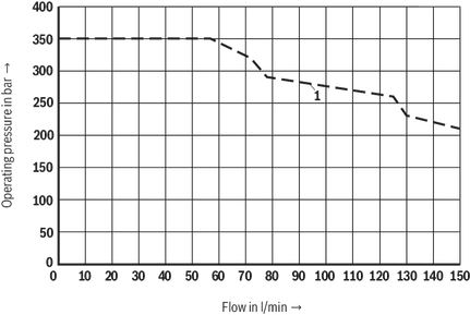

| Characteristic curve | Symbol |
| 1 | B |
Solenoid side
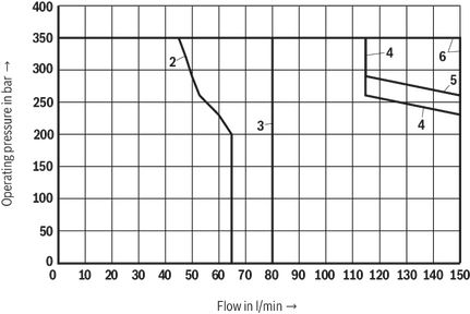
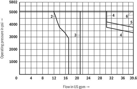
| Characteristic curve | Symbol |
| 2 | A, B |
| 3 | C; Y11 |
| 4 | D |
| 5 | Y |
| 6 | X7 |
Performance limits: 3 spool positions (measured with HLP46, ϑOil = 40 ±5 °C)
Notice!
The specified switching power limits are valid for use with two directions of flow (e. g. from P to A and simultaneous return flow from B to T).
Due to the flow forces acting within the valves, the admissible switching power limits may be considerably lower with only one direction of flow (e. g. from P to A while port B is blocked)!
In such use cases, please consult us!
The switching power limit was established while the solenoids were at operating temperature, at 10 % undervoltage and without tank preloading.
Spring side
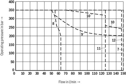
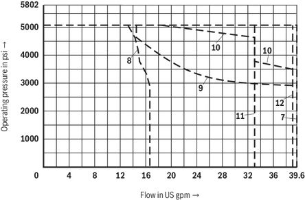
| Characteristic curve | Symbol |
| 7 | E |
| 8 | F |
| 9 | G |
| 10 | H |
| 11 | J; J19 |
| 12 | L |
Solenoid side
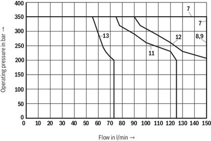
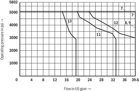
| Characteristic curve | Symbol |
| 7 | E |
| 8 | F |
| 9 | G |
| 11 | J, J19 |
| 12 | L |
| 13 | E34 |
Characteristic curves for symbols G41 and P upon request.
Notice!
The specified switching power limits are valid for use with two directions of flow (e. g. from P to A and simultaneous return flow from B to T).
Due to the flow forces acting within the valves, the admissible switching power limits may be considerably lower with only one direction of flow (e. g. from P to A while port B is blocked)!
In such use cases, please consult us!
The switching power limit was established while the solenoids were at operating temperature, at 10 % undervoltage and without tank preloading.
Solenoid side
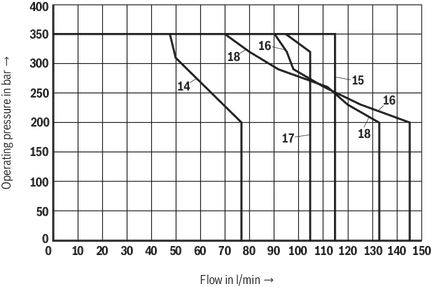
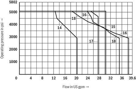
| Characteristic curve | Symbol |
| 14 | E67 |
| 15 | E ‒ „QS“ |
| 16 | U |
| 17 | R |
| 18 | W |
Symbols/Circuit diagrams
2 spool positions
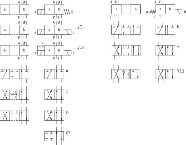
Notices!
- Representation according to DIN ISO 1219-1. Hydraulic interim positions are shown by dashes.
- Other symbols upon request
3 spool positions
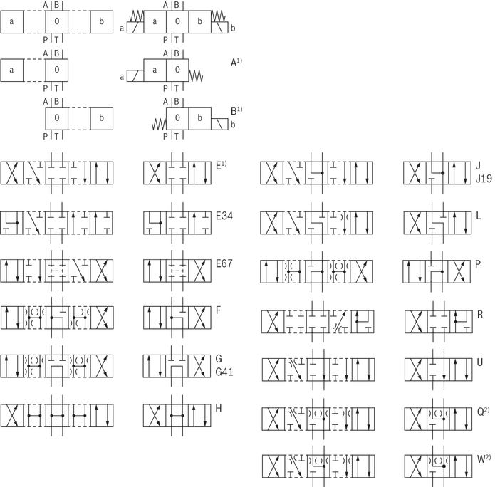
| 1) | Example: ● Symbol E with spool position “a” ordering code ..EA.. ● Symbol E with spool position “b” ordering code ..EB.. |
| 2) | For symbol Q and W, see “Flow cross-section" in the technical data |
Notices!
- Representation according to DIN ISO 1219-1. Hydraulic interim positions are shown by dashes.
- Other symbols upon request.
Inductive position switch type QM Switching logics
Version QMA
Position switch on side B, monitored spool position "a"
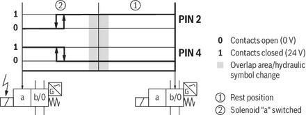
Version QMA
Position switch on side A, monitored spool position "a"

Version QMB
Position switch on side B, monitored spool position "b"

Version QMB
Position switch on side A, monitored spool position "b"

Version QM0
Position switch on side B, monitored rest position
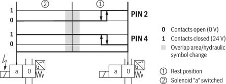
Version QM0
Position switch on side A, monitored rest position
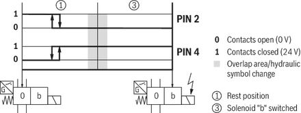
Inductive position switch type QL: switching logics
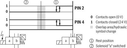
Version QLA
Position switch on side B, monitored spool position "a"

Version QLA
Position switch on side A, monitored spool position "a"
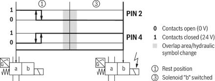
Version QLB
Position switch on side B, monitored spool position "b"
Version QLB
Position switch on side A, monitored spool position "b"
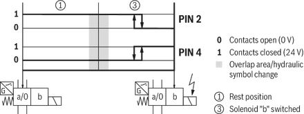
Inductive proximity sensor type QS: electrical connection
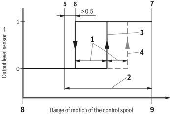
| 1 | Width depending on hysteresis and temperature drift |
| 2 | Overlap in the monitored spool position |
| 3 | Signal flow (in the switching position to be monitored) |
| 4 | Signal flow (leaving the monitored switching position) |
| 5 | Beginning of the overlap |
| 6 | Switching point |
| 7 | Stroke end |
| 8 | Not monitored spool position |
| 9 | Monitored spool position |
Inductive proximity sensor type QS: Switching logics
Version QSAG24W (valves with 3 spool positions, e.g. symbols E, J, G, …)
(Proximity sensor on side B, monitored spool position "a")
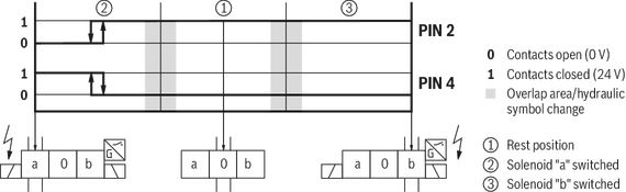
Version QSBG24W (valves with 3 spool positions, z. B. symbols E, J, G, …)
(Proximity sensor on side A, monitored spool position “b”)
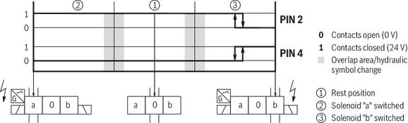
Version QS0G24W (valves with 3 spool positions, z. B. symbols E, J, G, …)
(Proximity sensor on side A and B, monitored rest position)

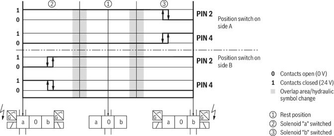
Version QSABG24W (valves with 3 spool positions, e.g. symbols E, J, G, …)
(Proximity sensor on side A and B, monitored spool position "a" and "b")
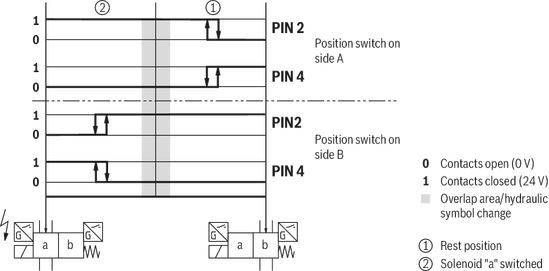
Version QSABG24W (valves with 2 spool positions, e. g. symbols A, B, D, Y, …)
(Proximity sensor on side A and B, monitored spool position "a" and "b")
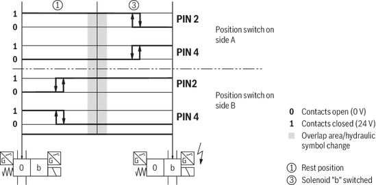
Version QS0BG24W (valves with 2 spool positions, e.g. symbols EB, …)
(Proximity sensor on side A and B, monitored spool position “0” and "b")
Version OF…QSAG24W
(Proximity sensor on side B, monitored spool position "a")
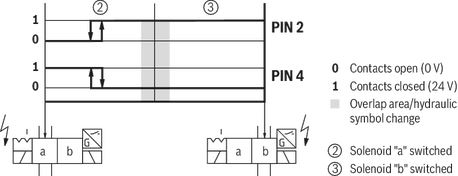
Version OF…QSBG24W
(Proximity sensor on side A, monitored spool position “b”)
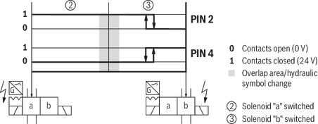
Version OF…QSABG24W
(Proximity sensor on side A and B, monitored spool position "a" and "b")
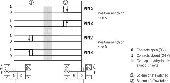
Electrical connection
Over-current fuse and switch-off voltage peaks
M12x1 plug-in connection ‒ Individual connection – “K72L”
Pin 5 without function

| Maximum admissible overvoltages according to DIN EN 60664-1:2008-01 (VDE 0110-1) (overvoltage category II): | |||
| Electrical connection 1) | Nominal voltage in V | Rated current in A | Maximum admissible Switch-off overvoltage in V 2) |
| K4, K4K | 12 | 3,72 | 500 |
| K4, K4K, K72L | 24 | 1,74 | 500 |
| K4, C4Z | 26 | 1,70 | 500 |
| K4 | 48 | 0,57 | 500 |
| K4 | 96 | 0,47 | 500 |
| K4 | 125 | 0,22 | 500 |
| K4, C4Z | 180 | 0,28 | 500 |
| K4 | 205 | 0,22 | 500 |
| K4 | 220 | 0,21 | 500 |
| 1) | Interference protection circuit integrated |
| 2) | To be ensured by user circuitry |
Notice:
When solenoid coils are switched off, voltage peaks result which may cause faults or damage in the connected control electronics. We therefore recommend limiting them to 2 x nominal voltage by means of an interference protection circuit. It must be noted that a diode switched in an antiparallel form extends the switching off time.
Electrical connections, assignment
| Electrical connections and coil connection combinations | |||||
| Ordering code connector | Top view | Circuit diagram | Pin | Connections, assignment | |
| 3-pole connector (2+PE) according to DIN EN 175301-803 | K4, K4K 1) | 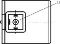 | 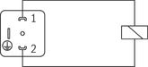 | 1 | Solenoid coil, polarity-independent |
| 2 | |||||
| Earthed | Earthing | ||||
| 4-pole connector according to IEC 60947-5-2, M12x1 with suppressor diode, only 24 V DC, integrated interference protection circuit and status LED | K72L | 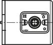 | 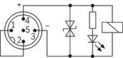 | 1 | Internal bridge |
| 2 | |||||
| 3 | Solenoid coil GND | ||||
| 4 | Solenoid coil 24 VDC supply voltage | ||||
| 5 | Without function | ||||
| 2-pole connector, type AMP Junior-Timer, rotated by 90° relative to valve axis | C4Z | 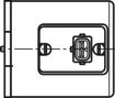 | 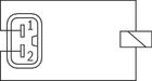 | 1 | Solenoid coil, polarity-independent |
| 2 | |||||
| 1) | M3, tightening torque maximum MA max = 0.5 Nm |
| 2) | Coil with potted-in connector base and sealing element to valve housing (IP67) |
Mating connectors according to DIN EN 175301-803
| For details and more mating connectors see data sheet 08006 | ||||||
| Connection | Valve side | Color | Material number | |||
| Without circuitry | With indicator light 12 ... 240 V | With rectifier 12 ... 240 V | With indicator light and Zener diode suppression circuit 24 V | |||
| M16 x 1,5 | a | gray | R901017010 | – | – | – |
| a/b | black | R901017011 | R901017022 | R901017025 | R901017026 | |
| 1/2″ NPT | a | red/brown | R900004823 | – | – | – |
| a/b | black | R900011039 | R900057453 | R900842566 | – | |
| Energy savings and fast switching 1) | |||
| Details see data sheet 30362 | |||
| Material number | |||
| Type VT-SSBA1-PWM-1X/V001/5 as fast switching amplifier (switching time reduction by approx. 50 %) 2) | Type VT-SSBA1-PWM-1X/V002/5 for energy reduction (energy saving by approx. 40 %) 3) | ||
| a/b | black | R901265633 | R901290194 |
| 1) | Only with J2 and X84; not for version “D” |
| 2) | Only for version “G12” and “K4/K4K” |
| 3) | Only for version “G24” and “K4/K4K” |
Cartridge with PWM connector according to data sheet 30362:
- Depending on the control spool, increasing the performance limit is possible.
- With version "G24" (energy saving), the coil temperature is reduced by ≥ [si]30 °C[s/i][imp]86 °F[/imp] for 100 % duty cycle.
Dimensions
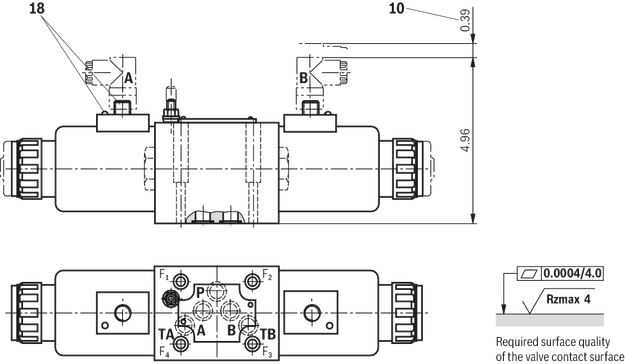
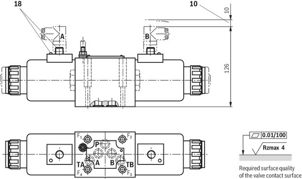
Dimensions in mm
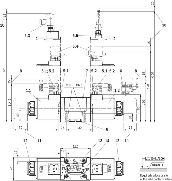
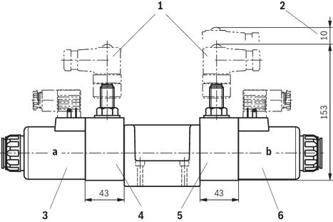
| 1.1 | Solenoid “a” |
| 1.2 | Solenoid “b” |
| 5.1 | Mating connector without circuitry for connector "K4", separate order, see "Accessories" |
| 5.2 | Mating connector without circuitry for connector "K4K" (separate order, see data sheet 08006) |
| 5.3 | Mating connector angled with M12x1 plug-in connection and status LED for connector "K72L", separate order, see "Accessories" |
| 5.4 | Double valve mating connector without/with circuitry for “K4” connector (separate order, see data sheet 08006) |
| 5.5 | Mating connector (AMP Junior Timer) for connector "C4Z" (separate order, see data sheet 08006) |
| 6 | Mating connector with circuitry for “K4” connector, separate order, see "Accessories" |
| 7 | Name plate |
| 8 | Identical seal rings for ports A, B, P, TA, TB |
| 9.1 | Name plate |
| 9.2 | Plug screw for valves with one solenoid |
| 10 | Identical seal rings for ports A, B, P, TA, TB |
| 11 | Plug screw for valves with one solenoid |
| 12 | Space required to remove the mating connector/angled socket |
| 13 | Space required to remove the coil |
| 14 | Mounting nut, tightening torque MA = 14.5±1.5 Nm |
Notice:
- Deviating from ISO 4401, port T is referred to as TA and port T1 is referred to as TB in this data sheet.
- The dimensions are nominal dimensions which are subject to tolerances.
Subplates according to data sheet 45054 (separate order)
G 66/01 (G3/8)
G 67/01 (G1/2)
G 534/01 (G3/4)
G 66/12 (SAE-6; 9/16-18)1)
G 67/12 (SAE-8; 3/4-16)1)
G 534/12 (SAE-12; 1-1/16-12)1)
1) upon request
Valve mounting screws (separate order)
4 hexagon socket head cap screws, metric
ISO 4762 - M6 x 40 - 10.9-flZn-240h-L
(friction coefficient μtotal = 0.09 to 0.14);
tightening torque MA = 12.5 Nm ± 10 %,
material no. R913000058
or
4 hexagon socket head cap screws
ISO 4762 - M6 x 40 - 10.9 (self procurement)
(friction coefficient µtotal = 0.12 to 0.17);
tightening torque MA = 15.5 Nm ± 10 %
4 hexagon socket head cap screws UNC
1/4-20 UNC x 1-1/2″ ASTM-A574
(friction coefficient µtotal = 0.19 to 0.24);
Tightening torque MA = 25 Nm ± 15 %,
(friction coefficient µtotal = 0.12 to 0.17);
tightening torque MA = 19 Nm ± 10 %,
material no. R978800710
With different friction coefficients, the tightening torques are to be adjusted accordingly!
Manual override
Dimensions in mm
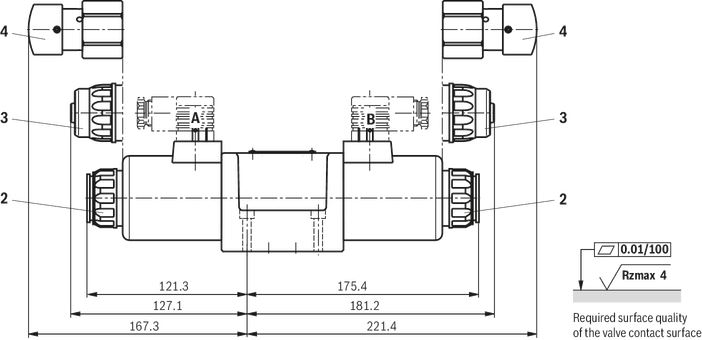
| 2 | Version without and with concealed manual override "N9" (standard) |
| 3 | Version with concealed manual override and protective cap "N8". (The protective cap must be removed prior to actuation.) |
| 4 | Version with manual override "N5" and “N6” |
Notice:
The dimensions are nominal dimensions which are subject to tolerances.
Subplates according to data sheet 45054 (separate order)
G 66/01 (G3/8)
G 67/01 (G1/2)
G 534/01 (G3/4)
G 66/12 (SAE-6; 9/16-18)1)
G 67/12 (SAE-8; 3/4-16)1)
G 534/12 (SAE-12; 1-1/16-12)1)
1) upon request
Valve mounting screws (separate order)
4 hexagon socket head cap screws, metric
ISO 4762 - M6 x 40 - 10.9-flZn-240h-L
(friction coefficient μtotal = 0.09 to 0.14);
tightening torque MA = 12.5 Nm ± 10 %,
material no. R913000058
or
4 hexagon socket head cap screws
ISO 4762 - M6 x 40 - 10.9 (self procurement)
(friction coefficient µtotal = 0.12 to 0.17);
tightening torque MA = 15.5 Nm ± 10 %
4 hexagon socket head cap screws UNC
1/4-20 UNC x 1-1/2″ ASTM-A574
(friction coefficient µtotal = 0.19 to 0.24);
Tightening torque MA = 25 Nm ± 15 %,
(friction coefficient µtotal = 0.12 to 0.17);
tightening torque MA = 19 Nm ± 10 %,
material no. R978800710
With different friction coefficients, the tightening torques are to be adjusted accordingly!
Spool position monitoring
Dimensions in mm
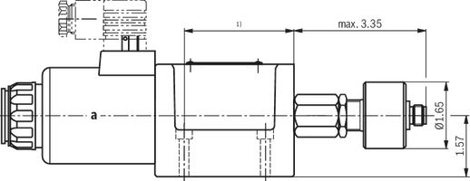
Inductive position switch type QM
Dimensions in mm
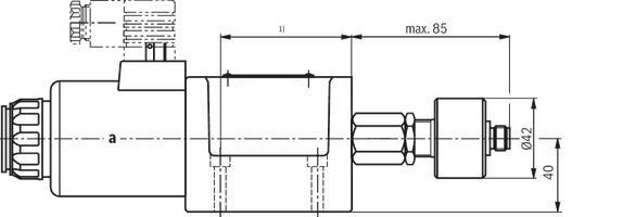
| 1) | For dimensions, see valve dimensions |
Notice:
The dimensions are nominal dimensions which are subject to tolerances.
Spool position monitoring
Inductive position switch type QL
Dimensions in mm
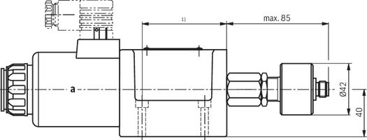
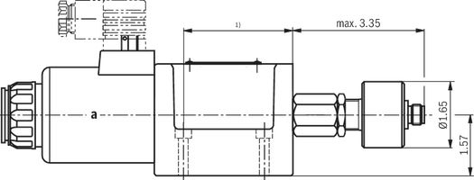
| 1) | For dimensions, see valve dimensions |
Mounting cavity R/T-11A; 3 main ports; thread M20 x 1.5 mm
Dimensions in mm
Notice!
The dimensions are nominal dimensions which are subject to tolerances.
Spool position monitoring
Inductive position switch type QS
Dimensions in mm
Mounting cavity, 2 main ports; M20 x 1.5 thread
Version "C"
Dimensions in mm
Notice:
The dimensions are nominal dimensions which are subject to tolerances.
M12x1 plug-in connection ‒ Individual connection
Dimensions in mm
Type 5-.WE 10 .3X/.CG24.K72L…
Dimensions in mm
Project planning information
| Temperature range and maximum operating pressure in case of use at low temperatures | ||
| Port | Pressure | Temperature range in °C |
| ‒ P, A, B, T | static 100 bar | –40 … –35 |
| ‒ P, A, B | dynamic from 100 bar to 350 barin linear form as a function of the temperature | –35 … –30 |
| ‒ T | dynamic from 100 bar to 210 bar in linear form as a function of the temperature | –35 … –30 |
| ‒ P, A, B, T | Maximum operating pressure | –30 … +50 |
Accessories
Mating connectors for valves with connector “K4”, without circuitry, standard
3P Z4
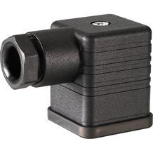
Mating connectors for valves with connector “K4”, without circuitry, standard
3P Z4
- For valves with connector “K4” according to EN 175301-803 and ISO 4400, 2-pole + PE, “large cubic connector”
- Mating connectors for valves with one or two solenoids (individual connection)
Mating connectors for valves with connector “K4”, without circuitry, standard
3P Z45
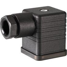
Mating connectors for valves with connector “K4”, without circuitry, standard
3P Z45
- For valves with connector “K4” according to EN 175301-803 and ISO 4400, 2-pole + PE, “large cubic connector”
- Mating connectors for valves with one or two solenoids (individual connection)
Mating connectors for valves with connector “K4”, with indicator light
3P Z5L
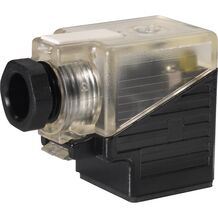
Mating connectors for valves with connector “K4”, with indicator light
3P Z5L
- For valves with connector “K4” according to EN 175301-803 and ISO 4400, 2-pole + PE, “large cubic connector”
- Mating connectors for valves with one or two solenoids (individual connection)
Mating connectors for valves with connector “K4”, with indicator light
3P Z55L
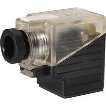
Mating connectors for valves with connector “K4”, with indicator light
3P Z55L
- For valves with connector “K4” according to EN 175301-803 and ISO 4400, 2-pole + PE, “large cubic connector”
- Mating connectors for valves with one or two solenoids (individual connection)
Mating connectors for valves with connector “K4”, with indicator light and Zener diode suppression circuit
3P Z5L1
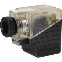
Mating connectors for valves with connector “K4”, with indicator light and Zener diode suppression circuit
3P Z5L1
- For valves with connector “K4” according to EN 175301-803 and ISO 4400, 2-pole + PE, “large cubic connector”
- Mating connectors for valves with one or two solenoids (individual connection)
Mating connectors for valves with connector “K4”, with rectifier
3P RZ5
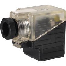
Mating connectors for valves with connector “K4”, with rectifier
3P RZ5
- For valves with connector “K4” according to EN 175301-803 and ISO 4400, 2-pole + PE, “large cubic connector”
- Mating connectors for valves with one or two solenoids (individual connection)
Mating connectors for valves with connector “K4”, with rectifier
3P RZ55
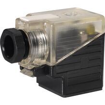
Mating connectors for valves with connector “K4”, with rectifier
3P RZ55
- For valves with connector “K4” according to EN 175301-803 and ISO 4400, 2-pole + PE, “large cubic connector”
- Mating connectors for valves with one or two solenoids (individual connection)
Downloads
 | Directional spool valves, direct operated, with solenoid actuation Data Sheet | RE23352 | 2015-09-01 | English | PDF | 972k Product Groups: Direct operated Type 5-.WE, 5-chamber version |

Цена по запросу
Нет отзывов об этом товаре.