
Артикул: RX7383
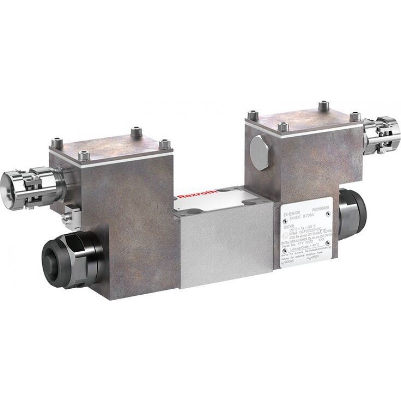
Directional spool valves, direct operated, with solenoid actuation WE 6…E..XE
Доступно к заказу
Цена по запросу
И выбери подходящего.
Description
- Size 6
- Component series 6X
- Maximum operating pressure 350 bar
- Maximum flow 70 l/min
- Area of application in accordance with the Explosion Protection Directive 2014/34/EU: II 2G; II 2D
- Type of protection valve:
– Ex h IIC T4 Gb X according to EN 80079-36
– Ex h IIIC T115°C Db X according to EN 80079-36 - Type of protection, solenoid coil:
– Ex eb mb IIC T4 Gb according to EN 60079-7 / EN 60079-18
– Ex tb IIIC T115°C Db according to EN 60079-31 - Solenoid coil certified according to IECEx
Features
- 4/3-, 4/2- or 3/2-way version
- For intended use in potentially explosive atmosphere
- Porting pattern according to ISO 4401-03-02-0-05
- Wet-pin DC or AC solenoids
- Electrical connection with individual connection and cable gland
- With manual override, optional
Product description
Directional valves of type WE are solenoid-actuated directional spool valves. They control the start, stop and direction of a flow.
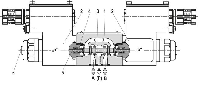
The directional valves basically consist of the housing (1), one or two solenoids (2), the control spool (3), and one or two return springs (4).
In the de-energized condition, the control spool (3) is held in the central position or in the initial position by the return springs (4) (except for impulse spools). The control spool (3) is actuated by wet-pin solenoids (2).
For unobjectionable functioning, the hydraulic system has to be bled properly.
The force of the solenoid (2) acts via the plunger (5) on the control spool (3) and pushes the latter from its rest position to the required end position. This enables the necessary direction of flow from P → A and B → T or P → B and A → T.
After de-excitation of the solenoid (2), the return spring (4) pushes the control spool (3) back to its rest position.
An optional manual override (6) allows control spool (3) to be moved without solenoid energization.
Without spring return "O" (only possible with symbols A, C and D)
This version is a directional valve with two spool positions and two solenoids without detent.
In the de-energized condition, there is no defined spool position.
With spring return "OF" (impulse spool, only possible with symbols A, C and D)
This version is a directional valve with two spool positions, two solenoids and one detent. It alternately locks the two spool positions and the solenoid therefore does not need to be permanently energized.
Notice:
Please observe a possible pressure conversion in the event of a differential cylinder. If pressure is led to the chamber on the piston side and the outflow of hydraulic fluid is blocked from the chamber on the rod side, it might lead to a pressure intensification and inadmissible high pressure on the rod side. This can damage cylinders, supply lines and connected valves.
Type 4WE 6 E6X/.E..NXE...
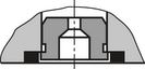
Throttle insert
The use of a throttle insert is required when, due to prevailing operating conditions, flows occur during the switching processes which exceed the performance limit of the valve.
Type code
| 01 | 02 | 03 | 04 | 05 | 06 | 07 | 08 | 09 | 10 | 11 | 12 | 13 | ||
| WE | 6 | 6X | / | E | XE | Z2 | / |
| 01 | 3 main ports | 3 |
| 4 main ports | 4 | |
| 02 | Directional valve | WE |
| 03 | Size 6 | 6 |
| 04 | Symbols; for the possible version, see "Symbols/Circuit diagrams" | |
| 05 | Component series 60 … 69 (60 … 69: unchanged installation and connection dimensions) | 6X |
| 06 | With spring return | no code |
| Without spring return | O | |
| Without spring return with detent | OF | |
| 07 | High-power solenoid, wet-pin | E |
| Electrical voltages | ||
| 08 | For ordering code see "Technical data" | e.g. G24 |
| 09 | Without manual override | no code |
| With manual override | N | |
| Explosion protection | ||
| 10 | “Increased safety”, for details, please refer to the "information on explosion protection" | XE |
| Electrical connection | ||
| 11 | Individual connection | |
| Solenoid with terminal box and cable gland, for details see "Electrical connection" | Z2 | |
| 12 | Without throttle insert | no code |
| Throttle Ø 0.8 mm | B08 | |
| Throttle Ø 1.0 mm | B10 | |
| Throttle Ø 1.2 mm | B12 | |
| Use with flows which exceed the performance limit of the valve, see "Product description" | ||
| Seal material (observe compatibility of seals with hydraulic fluid used, see "Technical data") | ||
| 13 | NBR seals | no code |
| FKM seals | V | |
Notice:
The manual override cannot be allocated a safety function and may only be used up to a tank pressure of 50 bar.
Technical data
general
| Size | 6 | ||
| Installation position | any | ||
| Ambient temperature range 1) | °C | -20 … +70 | |
| Storage temperature range | °C | +5 … +40 | |
| Maximum storage time | yrs | 1 | |
| Weight | Valve with one solenoid | kg | 2.6 |
| Valve with two solenoids | kg | 4 | |
| Surface protection | Galvanized | ||
| Maximum admissible acceleration amax | g | 10 | |
| 1) | Observe the "Special application conditions for safe application" |
hydraulic
| Size | 6 | ||
| Maximum operating pressure | Port P | bar | 350 |
| Port A | bar | 350 | |
| Port B | bar | 350 | |
| Port T 1) | bar | 210 | |
| Maximum flow | l/min | 70 | |
| Flow cross-section (spool position 0) | Symbol Q | approx. 6 % of nominal cross-section | |
| Symbol W | approx. 3 % of nominal cross-section | ||
| Hydraulic fluid | see table "Hydraulic fluid" | ||
| Hydraulic fluid temperature range | NBR seals | °C | -20 … +80 |
| FKM seals | °C | -15 … +80 | |
| Viscosity range | mm²/s | 2.8 … 500 | |
| Maximum admissible degree of contamination of the hydraulic fluid, cleanliness class according to ISO 4406 (c) 2) | Class 20/18/15 | ||
| 1) | With symbols A and B, port T must be used as leakage oil connection if the operating pressure exceeds the admissible tank pressure. |
| 2) | The cleanliness classes specified for the components must be adhered to in hydraulic systems. Effective filtration prevents faults and simultaneously increases the life cycle of the components. For the selection of the filters, see www.boschrexroth.com/filter. |
| Hydraulic fluid | Classification | Suitable sealing materials | Standards | data sheet | |
| Mineral oils | HL, HLP, HLPD | NBR, FKM | DIN 51524 | 90220 | |
| Bio-degradable | Insoluble in water | HETG | FKM | ISO 15380 | 90221 |
| HEES | FKM | ||||
| Soluble in water | HEPG | FKM | ISO 15380 | ||
| Flame-resistant | Containing water | HFC (Fuchs: Hydrotherm 46M, Renosafe 500; | NBR | ISO 12922 | 90223 |
|
Important information on hydraulic fluids:
| |||||
electrical
| Voltage type | Direct voltage | AC voltage | ||
| Nominal voltage according to VDE 0580 | V | 24 / 48 / 110 | 110 / 230 | |
| Voltage tolerance (nominal voltage) | % | ± 10 | ||
| Admissible residual ripple | % | < 5 | - | |
| Duty cycle/operating mode according to VDE 0580 | S1 (continuous operation) | |||
| Switching time according to ISO 6403 1) | ON | ms | 30 … 55 | 40 … 80 |
| OFF | ms | 10 … 15 | 40 … 50 | |
| Maximum switching frequency | 1/h | 15000 | 7200 | |
| Nominal power with ambient temperature 20 °C | W | 17 | ||
| Maximum power with 1.1 x nominal voltage and an ambient temperature of 20 °C | W | 20.6 | ||
| Protection class according to EN 60529 | IP66 (with correctly installed electrical connection) | |||
| 1) | The switching times were determined at a hydraulic fluid temperature of 40 °C and a viscosity of 46 mm2/s. Deviating hydraulic fluid temperatures can result in different switching times. Switching times change dependent on operating time and application conditions. |
Notice:
Solenoids for AC voltage are DC solenoids with integrated rectifier.
Information on explosion protection
| Area of application according to directive 2014/34/EU | II 2G | II 2D | |
| Type of protection of the valve according to EN 80079-36 1) | Ex h IIC T4 Gb X | Ex h IIIC T115°C Db X | |
| Maximum surface temperature 2) | °C | 115 | |
| Temperature class | T4 | ||
| Type of protection solenoid according to EN 60079-7 / EN 60079-18 / EN 60079-31 | Ex eb mb IIC T4 Gb | Ex tb IIIC T115°C Db | |
| Type examination certificate solenoid | BVS 20 ATEX E 009 X | ||
| “IECEx Certificate of Conformity” for solenoid | IECEx BVS 2007 X | ||
| 1) | Ex h: structural safety c according to EN 80079-37. |
| 2) | Surface temperature > 50 °C, provide contact protection. |
Special application conditions for a safe application
- Connection lines must be passed in a strain-relieved way. The first mounting point must be within 150 mm of the cable and line entry.
- In case of valves with two solenoids, maximally one of the solenoids may be energized at a time.
- A simultaneous power supply of several valves in bank assembly is possible if the ambient temperature does not exceed 60 °C.
- In case of bank assembly, if only one of the solenoids is energized at a time, and during individual operation, the maximum ambient temperature may not exceed 70 °C.
- The maximum temperature of the surface of the valve jacket is 115 °C. This has to be considered when selecting the connection cable and/or contact of the connection cable with the surface of the jacket is to be prevented.
(For applications outside these values, please consult us!)
Diagrams/characteristic curves
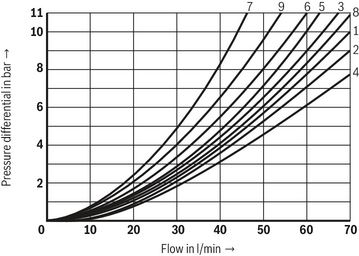
(measured with HLP46, ϑOil = 40 ±5 °C)
Δp-qV characteristic curves
Δp-qV characteristic curves
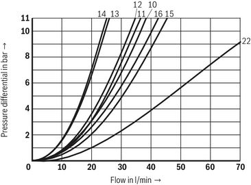
Δp-qV characteristic curves
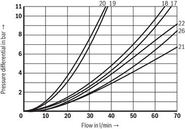
Δp-qV characteristic curves
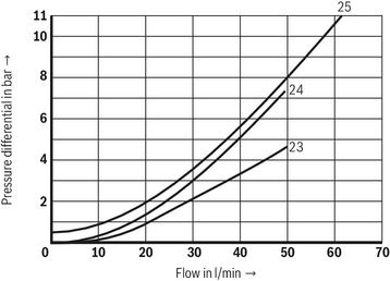
| Symbol | Direction of flow | |||||
| P – A | P – B | A – T | B – T | B – A | P – T | |
| A, B | 3 | 3 | – | – | – | – |
| A9 | 15 | 16 | – | – | – | – |
| B9 | 12 | 10 | – | – | – | – |
| C | 1 | 1 | 3 | 1 | – | – |
| D46, D, Y | 5 | 5 | 3 | 3 | – | – |
| E | 3 | 3 | 1 | 1 | – | – |
| G | 6 | 6 | 8 | 8 | – | 7 |
| G3 | 6 | – | – | 8 | – | 7 |
| G73 | 14 | 14 | 13 | 13 | – | 11 |
| H | 2 | 4 | 2 | 2 | – | 8 |
| J, Q | 1 | 1 | 2 | 1 | – | – |
| M | 2 | 4 | 3 | 3 | – | – |
| P | 3 | 1 | 1 | 1 | – | – |
| U | 3 | 3 | 8 | 4 | – | – |
| T | 9 | 9 | 8 | 8 | – | 7 |
| V | 1 | 2 | 1 | 1 | – | – |
| W | 1 | 1 | 2 | 2 | – | – |
| X36A | 6 | – | 9 | 22 | – | – |
| J73 | 19 | 20 | 18 | 17 | – | – |
| X7 | 22 | – | – | 21 | – | – |
| J32 | 17 | – | – | 26 | – | – |
| D19 | 23 | – | 25 | 24 | – | – |
Performance limits
(measured with HLP46, ϑOil = 40 ±5 °C)
Notice:
The specified performance limits are valid for operation with two directions of flow (e.g. from P to A and simultaneous return flow from B to T).
Due to the flow forces acting within the valves, the possible performance limit may be considerably lower with only one direction of flow (e.g. from P to A while port B is blocked).
The performance limits were determined when the solenoids were at operating temperature, at 10% undervoltage and without tank preloading.
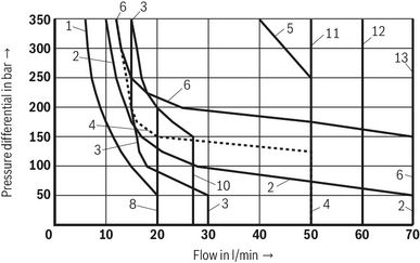
Version "G24"
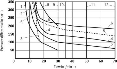
| Characteristic curve | Symbol |
| 1 | A, B |
| 2 | J, U |
| 3 | V |
| 4 | D, C, Y |
| 5 | Q, W |
| 6 | E |
| 8 | P |
| 9 | T |
| 10 | G |
| 11 | H, D/OF, C/OF |
| 12 | M, D/O, C/O |
Version "G24"
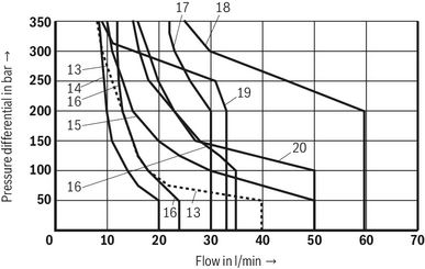
| Characteristic curve | Symbol |
| 13 | A9 / B9 |
| 14 | E67 |
| 15 | J19 |
| 16 | J73 |
| 17 | G73 |
| 18 | X7 |
| 19 | X36A |
| 20 | G3 |
Version "G48", "G110", "W110" and "W230"
| Characteristic curve | Symbol |
| 1 | A, B |
| 2 | J, U, Q, W |
| 3 | V |
| 4 | D, C, Y |
| 5 | D46/OF |
| 6 | E |
| 8 | P, T |
| 10 | G |
| 11 | H |
| 12 | D/OF, C/OF |
| 13 | M, D/O, C/O |
Version "G48", "G110", "W110" and "W230"
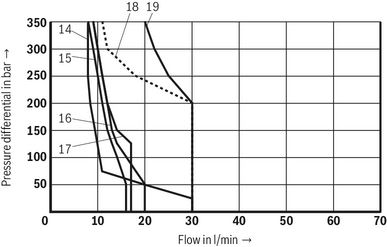
| Characteristic curve | Symbol |
| 14 | B9 |
| 15 | J32 |
| 16 | J19 |
| 17 | D19 |
| 18 | X7 |
| 19 | G73 |
Symbols/Circuit diagrams
2 spool positions
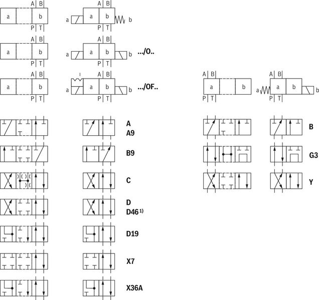
| 1) | For valves with AC solenoids and detent, only D46/OF is admissible. |
3 spool positions
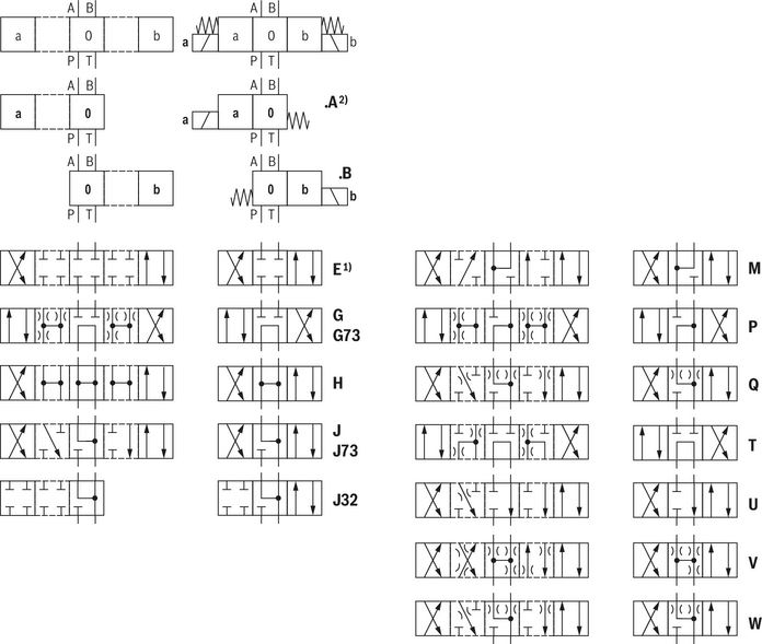
| 1) | Example: Symbol E with spool position "a" → ordering code ..EA.. |
Notice:
Representation according to ISO 1219-1.
Hydraulic interim positions are shown by dashes.
Electrical connection
The type-examination tested solenoid coil of the valve is equipped with a terminal box, a type-examination tested cable entry and a type-examination tested blind plug.
The connection is polarity-independent.
Solenoid coils to be connected to AC voltage are equipped with an integrated rectifier.
Notice:
When establishing the electrical connection, the protective grounding conductor (PE) must be connected correctly.
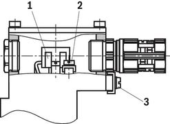
Properties of the connection terminals and mounting elements
| Position | Function | Connectable line cross-section |
| 1 | Operating voltage connection | Single-wire 0.75 … 2.5 mm2 Finely stranded,0.75 … 1.5 mm2 |
| 2 | Connection for protective earthing conductor | Single-wire 2.5 mm2 max. Finely stranded, 1.5 mm2 max. |
| 3 | Connection for potential equalization conductor | Single-wired, 4 … 6 mm2 Finely stranded, min. 4 mm2 |
Connection line
| Line type | Non-armored and non-shielded connection lines | |
| Temperature range | °C | ≤ -20 … ≥ +110 |
| Line diameter | mm | 7 ... 10.5 |
| Direct voltage, polarity-independent | AC voltage |
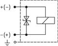 | 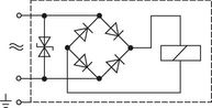 |
Notice:
Only use finely stranded conductors if they have pressed-on wire end ferrules.
Over-current fuse and switch-off voltage peaks
| Voltage data in the valve type code | Nominal voltage valve solenoid | Rated current valve solenoid | Rated current for external miniature fuse: Medium time-lag (M) according to DIN 41571 and EN/IEC 60127 | Rated voltage of external miniature fuse: Medium time-lag (M) according to DIN 41571 and EN/IEC 60127 | Maximum voltage value when switching off | Interference protection circuit |
| G24 | 24 VDC | 0.708 ADC | 800 mA | 250 V | –90 V | Suppressor diode bi-directional |
| G48 | 48 VDC | 0.354 ADC | 400 mA | 250 V | –200 V | |
| G110 | 110 VDC | 0.155 ADC | 200 mA | 250 V | –390 V | |
| W110R | 110 VAC | 0.163 AAC | 200 mA | 250 V | –3 V | Bridge rectifier and suppressor diode |
| W230R | 230 VAC | 0.078 AAC | 80 mA | 250 V | –3 V |
Notices:
A fuse which corresponds to the rated current according to DIN 41571 and EN/IEC 60127 has to be connected upstream of every valve solenoid (max. 3 x Irated).
The shut-off threshold of the fuse has to match the prospective short-circuit current of the supply source.
The short-circuit current of the supply source to be expected may amount to a maximum of 1500 A.
This fuse may only be installed outside the potentially explosive atmosphere or must be of an explosion-proof design.
When inductivities are switched off, voltage peaks result which may cause faults in the connected control electronics.
Dimensions
Dimensions in mm
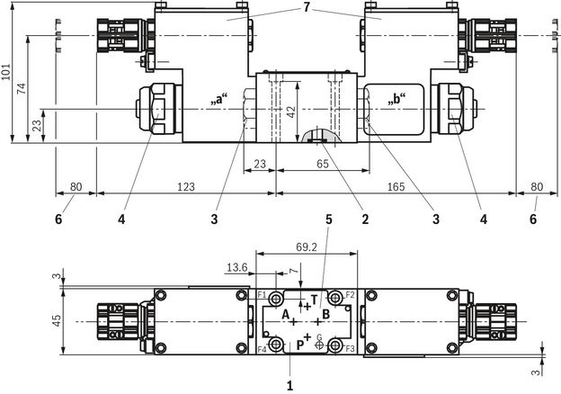
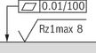 |
| Required surface quality of the valve contact surface |
| 1 | Name plate |
| 2 | Identical seal rings for ports A, B, P, T |
| 3 | Plug screw for valves with one solenoid |
| 4 | Mounting nut with hexagon SW32 |
| 5 | Porting pattern according to ISO 4401-03-02-0-05 |
| 6 | Space required to remove the solenoid coil |
| 7 | Terminal box |
Valve mounting screws (separate order)
| Size | Quantity | Hexagon socket head cap screws | Material number |
| 6 | 4 | ISO 4762 - M5 x 50 - 10.9 (Friction coefficient μtotal = 0.09 … 0.14) Tightening torque MA = 7 Nm ±10 % | R913043758 |
| Only use valve mounting screws with the listed thread diameters and strength properties. Observe the screw-in depth. |
Subplates (separate order) with porting pattern according to ISO 4401-03-02-0-05, see data sheet 45100.
Notices:
- Subplates are no components in the sense of directive 2014/34/EU and can be used after the manufacturer of the overall system has conducted an assessment of the risk of ignition. The "G...J3" versions are free from aluminum and/or magnesium and galvanized.
- The dimensions are nominal dimensions which are subject to tolerances.
Installation conditions
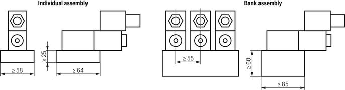
(Dimensions in mm)
|
| Individual assembly | Bank assembly |
| Subplate dimensions | Minimum dimensions: | Minimum cross-section: |
| Thermal conductivity of the subplate | ≥ 36.2 W/mK | |
| Minimum distance between the longitudinal valve axes | ≥ 55 | |
Dimensions in mm
Notice:
Please observe the "Special conditions for safe use".
Accessories
Subplates
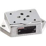
Subplates
Downloads
 | Directional spool valves, direct operated, with solenoid actuation Data Sheet | RE23178-XE | 2020-11-01 | English, United States | PDF | 750k Product Groups: Direct operated Type WE …XE |
| Directional spool valves,direct operated,with solenoid actuation Manual | RE23178-XE-B | 2020-10-01 | English | PDF | 2MB Product Groups: On/off valves Type WE6..6X/...XE... |
| Explosion-protected hydraulic products for industrial and mobile applications Brochure | R999000373 | 2017-03-01 | English | PDF | 5.8MB Product Groups: Pumps, CD - single rod cylinder, Proportional, high-response and servo valves, Axial piston pumps, Mobile controls Product overview |

Нет отзывов об этом товаре.