
Доступно к заказу
Цена по запросу
И выбери подходящего.
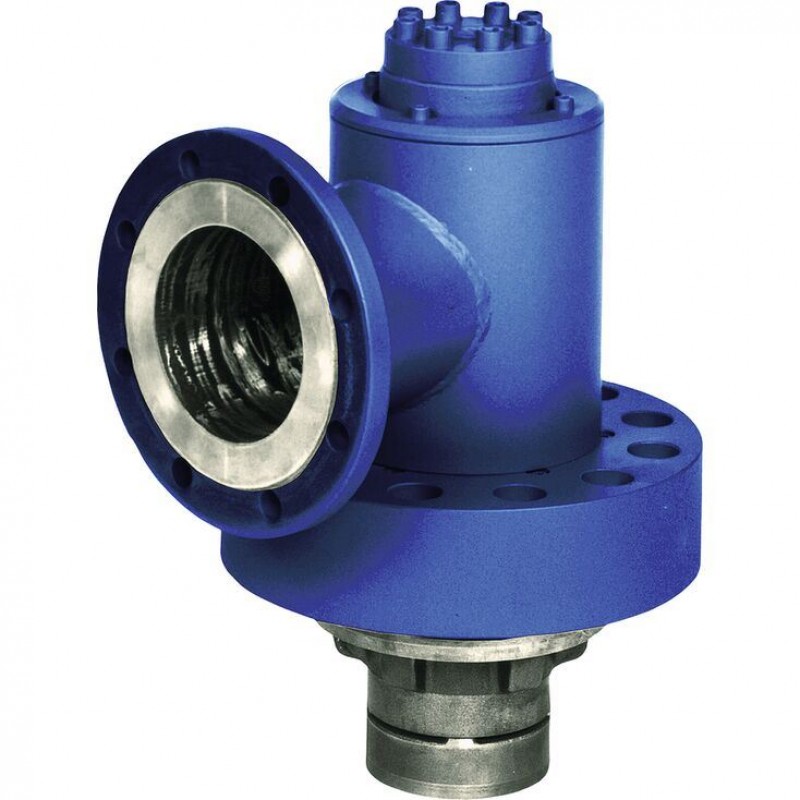
Description
- Size 125 … 500
- Component series 4X
- Maximum operating pressure 350 bar
- Maximum flow 50000 l/min
Features
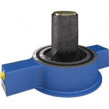
- Pilot operated check valve, with or without pre-decompression
- Flange connection
- Tank installation
- Cartridge valve without control open spool (check valve)
- Reduced switching noises due to damping measures
- Rotatable low-pressure connection (housing)
- Inductive position switch, optional
- Higher operating pressures, on request
Product description
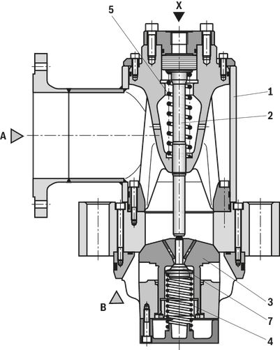
Type SF . .1-1-4X/…
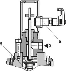
Type SF . A0-1-4X/Q2G24Z
Type SF . .0-1-4X/…
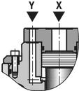
Type SF . .0-1-4X/…
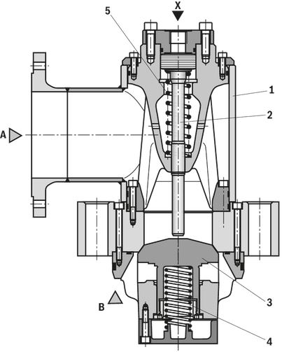
Type SF 500 .1-1-4X/…
| 1 | Housing with low-pressure flange, continuously rotatable |
| 2 | Name plate |
| 3 | Control cylinder |
| 4 | Connection G1 1/2 (draining); tightening torque MA = 300 Nm ±10 % |
| 5 | Ring |
| 6 | Mounting screws |
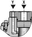
| 7 | Port Y; connection flange on request |
| 8 | Port X; connection flange on request |
| 9 N1 | Number of the flange mounting screws evenly arranged at the circumference (type of connection "A") |
| 10 N2 | Number of the valve mounting screws evenly arranged at the circumference |
| 11 | Version "without position switch" |
| 12 | Version "Q2G24Z" |
Type code
| 01 | Prefill valve | SF |
| 02 | Size 125 | 125 |
| Size 150 | 150 | |
| Size 200 | 200 | |
| Size 250 | 250 | |
| Size 300 | 300 | |
| Size 350 | 350 | |
| Size 400 | 400 | |
| Size 500 (only version "A" and "B") | 500 | |
| 03 | Flange connection | A |
| Tank installation | B | |
| Screw-in cartridge valve without control spool (check valve) | K | |
| 04 | without pre-decompression | 0 |
| With pre-decompression | 1 | |
| Spring feedback of the main poppet | ||
| 05 | Cracking pressure ≈ 0.2 bar | 1 |
| 06 | Component series 40 to 49 (40 to 49: unchanged installation and connection dimensions) | 4X |
| Spool position monitoring | ||
| 07 | Without position switch | no code |
| With inductive position switch, position monitoring "open", with connector plug (only version "A0") | Q2G24Z | |
| Seal material | ||
| 08 | NBR seals | no code |
| Other seals on request | ||
| Connection thread | ||
| 09 | Pipe thread according to ISO 228-1 | no code |
| Special version | ||
| 10 | Standard | no code |
| Operating pressure 420 bar (restricted size selection, please contact us) | SO102 | |
| Operating pressure 500 bar (restricted size selection, please contact us) | SO104 | |
| 11 | Further details in the plain text | * |
| 01 | 02 | 03 | 04 | 05 | 06 | 07 | 08 | 09 | 10 | 11 | |||
| SF | – | 1 | – | 4X
| / | * |
Technical data
general
| Nenngröße | 125 | 150 | 200 | 250 | 300 | 350 | 400 | 500 | ||
| Masse | Version "A" | kg | 75 | 135 | 185 | 365 | 625 | 1200 | 1580 | 3400 |
| Version "B" | kg | 60 | 105 | 145 | 295 | 545 | 1000 | 1400 | 3100 | |
| Version "K" | kg | 45 | 90 | 105 | 205 | 355 | 670 | 950 | - | |
| Installation position | any | |||||||||
hydraulic
| Size | 125 | 150 | 200 | 250 | 300 | 350 | 400 | 500 | ||
| Maximum operating pressure | Anschluss A | bar | 16 | |||||||
| Port B | bar | 350 | ||||||||
| Anschluss X | bar | 350 | ||||||||
| Port Y | bar | 350 | ||||||||
| Cracking pressure 1) | bar | ≈ 0.2 | ||||||||
| Maximum flow 2) | Case of application 1 | l/min | 2500 | 3900 | 5600 | 10000 | 15600 | 22480 | 30600 | 50000 |
| Case of application 2 | l/min | 2500 | 3900 | 5600 | 10000 | 14000 | 19050 | 24880 | 40000 | |
| Case of application 3 | l/min | 1700 | 2440 | 4340 | 6775 | 9750 | 13280 | 17340 | 28000 | |
| Case of application 4 | l/min | 1470 | 2120 | 3770 | 5890 | 8480 | 11540 | 15080 | 25000 | |
| Case of application 5 | l/min | 590 | 850 | 1510 | 2360 | 3400 | 4620 | 6050 | ||
| Druckflüssigkeit | see table | |||||||||
| Hydraulic fluid temperature range | °C | -30 … +80 | ||||||||
| Viscosity range | mm²/s | 10 … 800 | ||||||||
| Maximum admissible degree of contamination of the hydraulic fluid 3) | Class 20/18/15 according to ISO 4406 (c) | |||||||||
| 1) | Pressure differential at the main poppet for overcoming the spring force |
| 2) | A to B, Δp = 0.3 bar |
| 3) | The cleanliness classes specified for the components must be adhered to in hydraulic systems. Effective filtration prevents faults and simultaneously increases the life cycle of the components. For the selection of the filters, see www.boschrexroth.com/filter. |
| Hydraulic fluid | Classification | Suitable sealing materials | Standards | |
| Mineral oils and related hydrocarbons | HL, HLP, HVLP | NBR, FKM 3) | DIN 51524 | |
| Bio-degradable | Insoluble in water | HETG | NBR, FKM 3) | VDMA 24568 |
| HEES | FKM 3) | |||
| Soluble in water | HEPG | FKM 3) | VDMA 24568 | |
| Flame-resistant | Water-free | HFDU, HFDR | FKM 3) | ISO 12922 |
| HFC | NBR | ISO 12922 | ||
Important information on hydraulic fluids!Flame-resistant and bio-degradable: | ||||
| 3) Upon request |
Flow ‒ case of application 1 (A to B)
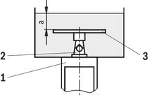
Flow ‒ case of application 2 (A to B)
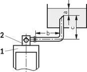
Flow ‒ case of application 3 (A to B)
Size of the filling tank at least 1.5 x cylinder content
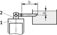
Flow ‒ case of application 4 (A to B)
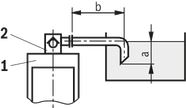
Flow ‒ case of application 5 (A to B)
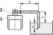
Notice!
An underdimensioned prefill valve and/or an underdimensioned line leads to gas leaks from the hydraulic fluid with corresponding consequences and often to long-term damage at the cylinder seals.
For boundary areas, please ask us!
Information on case of application 1 to 5
For limit areas, please contact us. It is often enough, to select a pipeline which is one size larger.
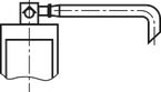
| 1 | Cylinders |
| 2 | Prefill valve |
| 3 | This sheet is not included in the scope of delivery. With smaller tank dimensions and minimum hydraulic fluid level (a), it prevents the formation of tunnels. |
| a | at least 300 mm with extended cylinder |
| b | up to 1000 mm with the specified maximum flows |
| c | h ≤ 500 mm |
| h | 300 mm ≤ h < 500 mm |
(For applications outside these values, please consult us!)
Diagrams/characteristic curves
(measured with HLP46, ϑOil = 40 ±5 °C)
Δp-qv characteristic curves – NG125 … 250 (A → B)
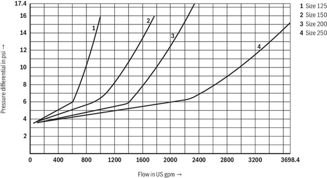
Δp-qv characteristic curves – NG125 … 250 (A → B)
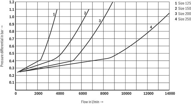
Δp-qv characteristic curves – NG125 … 250 (B → A)

Δp-qv characteristic curves – NG125 … 250 (B → A)

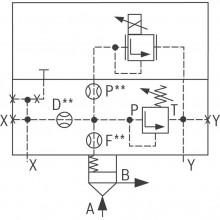
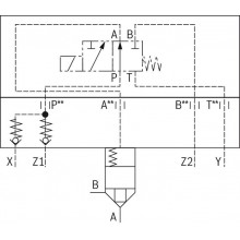
Symbols/Circuit diagrams
Version "A" and "B" (NG125 to 400)

Version "A" and "B" (NG500)

Version "K" (NG125 to 400)

Dimensions
load errorDownloads


Цена по запросу
Цена по запросу


Нет отзывов об этом товаре.