
Доступно к заказу
Цена по запросу
И выбери подходящего.
Description
- Size 6
- Component series 5X
- Maximum primary operating pressure 315 bar
- Maximum flow 60 l/min
- Area of application in accordance with the Explosion Protection Directive 2014/34/EU: I M2; II 2G
- Type of protection of the valve solenoids: c (EN 13463-5)
- Size 6
- Component series 5X
- Maximum operating pressure 315 bar
- Maximum flow 60 l/min
- Area of application in accordance with the Explosion Protection Directive 2014/34/EU: I M2; II 2G
- Type of protection of the valve solenoids: c (EN 13463-5)
Features
- For subplate mounting
- Porting pattern according to ISO 4401-03-02-0-05 (but without locating hole)
- Check valve, optional
Product description
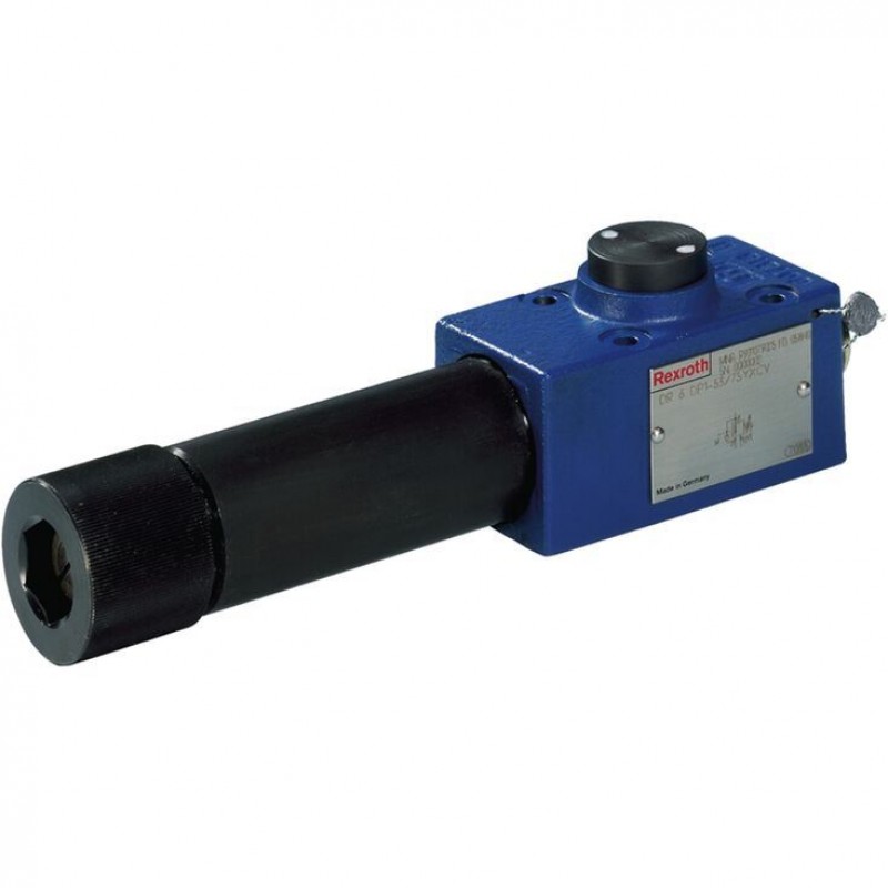
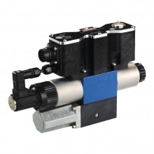
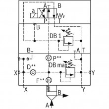
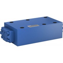
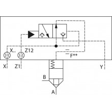
The valve type DR 6 DP...XC is a direct operated pressure reducing valve in subplate mounting design and 3-way version, i. e. with pressure limitation of the secondary circuit.
It is used to limit a system pressure.
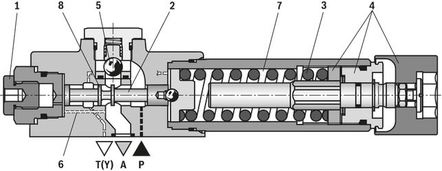
The secondary pressure can be set via the adjustment element (4).
The valve is open in initial position. Hydraulic fluid can flow from channel P to channel A without restrictions. The pressure in channel A is simultaneously applied via the control line (6) at the piston area opposite the compression spring (3). If the pressure in channel A exceeds the value set at the compression spring (3), the control spool (2) moves to control position and keeps the set pressure in channel A at a constant level.
Control signal and pilot oil come internally via the control line (6) from channel A.
If the pressure in channel A increases further due to an external force effect at the actuator, it pushes the control spool (2) even further against the compression spring (3).
In this way, channel A is connected to the tank via the control edge (8) at the control spool (2). So much hydraulic fluid is discharged into the tank, that the pressure can no longer increase.
The leakage oil drain from the spring chamber (7) is always effected externally via channel T (Y).
For the free flow back from channel A to channel P, a check valve (5) can optionally be installed.
A pressure gauge connection (1) allows for the control of the secondary pressure.
Type DR 6 DP1-5X/...XCYV
Type code
| 01 | 02 | 03 | 04 | 05 | 06 | 07 | 08 | 09 | 10 | 11 | ||
| DR | 6 | 1 | – | 5X | / | Y | XC | V |
| 01 | Subplate mounting | no code |
| 02 | Pressure reducing valve, direct operated | DR |
| 03 | Size 6 | 6 |
| Pressure reduction in | ||
| 04 | Channel P | DP |
| Adjustment type | ||
| 05 | Rotary knob | 1 |
| 06 | Component series 50 … 59 (50 … 59: unchanged installation and connection dimensions) – subplate mounting | 5X |
| Maximum secondary pressure | ||
| 07 | 25 bar | 25 |
| 75 bar | 75 | |
| 150 bar | 150 | |
| 210 bar | 210 | |
| 315 bar1) | 315 | |
| Pilot oil flow | ||
| 08 | Internal pilot oil supply, external leakage oil drain | Y |
| 09 | With check valve | no code |
| Without check valve | M | |
| Explosion protection | ||
| 10 | "Structural safety", for details, please refer to the "Information on explosion protection" | XC |
| Seal material | ||
| 11 | FKM seals | V |
| Observe compatibility of seals with hydraulic fluid used. (Other seals upon request) | ||
| 1) | Without check valve "M" |
Technical data
(For applications outside these values, please consult us!)
general
| Size | 6 | ||
| Installation position | any | ||
| Ambient temperature range | NBR seals | °C | -30 … +80 |
| FKM seals | °C | -20 … +80 | |
| Storage temperature range | NBR seals | °C | -30 ... +80 |
| FKM seals | °C | -20 ... +80 | |
| Weight | kg | 1.2 | |
| Surface protection | Standard: Coating, layer thickness max. 100 μm | ||
hydraulic
| Size | 6 | ||
| Maximum primary operating pressure | bar | 315 | |
| Maximum secondary pressure 1) | bar | 25 75 150 210 315 | |
| Maximum counter pressure | Port T (Y) | bar | 50 |
| Maximum flow | l/min | 60 | |
| Hydraulic fluid | see table "Hydraulic fluid" | ||
| Hydraulic fluid temperature range | NBR seals | °C | -30 … +80 |
| FKM seals | °C | -20 … +80 | |
| Viscosity range | mm²/s | 10 … 800 | |
| Maximum admissible degree of contamination of the hydraulic fluid 2) | Class 20/18/15 according to ISO 4406 (c) | ||
| 1) | To avoid exceeding the maximum admissible secondary pressure, the pressure must be checked using a suitable measuring device during adjustments. |
| 2) | The cleanliness classes specified for the components must be adhered to in hydraulic systems. Effective filtration prevents faults and simultaneously increases the life cycle of the components. For the selection of the filters, see www.boschrexroth.com/filter. |
| Hydraulic fluid | Classification | Suitable sealing materials | Standards | Data sheet |
| Mineral oils | HL, HLP | NBR, FKM | DIN 51524 | 90220 |
| Important information on hydraulic fluids:
| ||||
Information on explosion protection
| Area of application according to directive 2014/34/EU | IM2, II2G | |
| Type of protection valve | c (EN 13463-5) | |
| Maximum surface temperature 1) | °C | 125 |
| Temperature class | T4 | |
| 1) | Due to the arising surface temperatures of the solenoid coils, the standards ISO 13732-1 and ISO 4413 are to be observed. |
Diagrams/characteristic curves
(measured with HLP46, ϑOil = 40 ±5 °C)
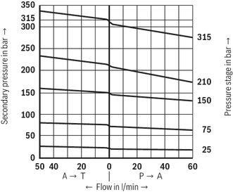
pA-qV characteristic curves
Notices:
- The curve development is maintained according to the pressure rating if a lower pressure is set.
- The characteristic curves for the pressure relief function apply to an output pressure = 0 over the entire flow range.
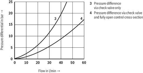
Δpmin-qV characteristic curves

Δp-qV characteristic curves
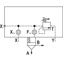
Symbols/Circuit diagrams
Version "YM"
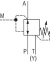
Version “Y”
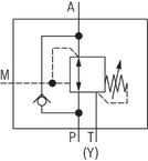
Dimensions
load errorDownloads
 | Explosion-protected hydraulic products for industrial and mobile applications Brochure | R999000373 | 2017-03-01 | English | PDF | 5.8MB Product Groups: Pumps, CD - single rod cylinder, Proportional, high-response and servo valves, Axial piston pumps, Mobile controls Product overview |

Цена по запросу

Цена по запросу
Нет отзывов об этом товаре.