
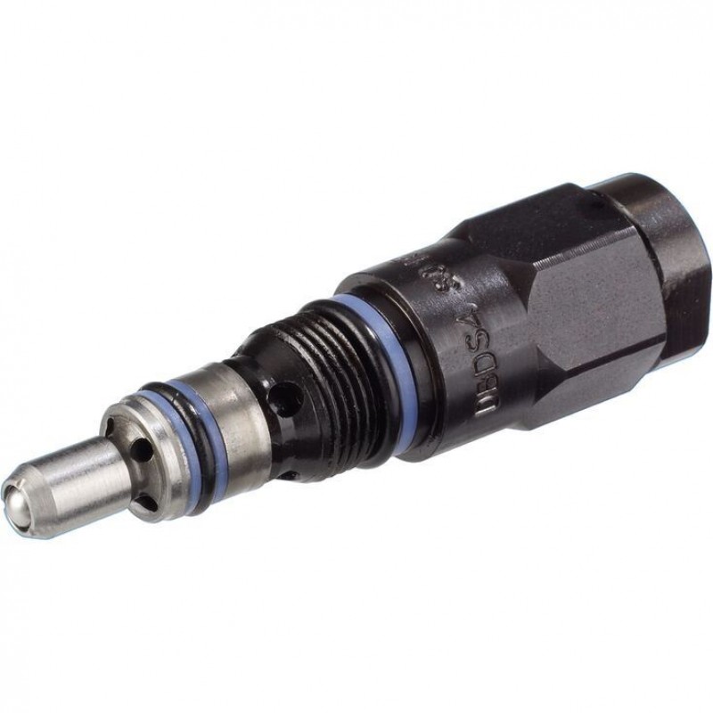
Доступно к заказу
Цена по запросу
И выбери подходящего.
Description
- Size 4
- Component series 1X
- Maximum operating pressure 500 bar
- Maximum flow 20 l/min
Features
- Cartridge valve
- 8 pressure ratings
- 2 adjustment types, optionally:
• Grub screw with internal hexagon
• Hand wheel
Product description
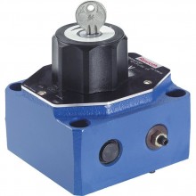
The pressure valve type DBD..K.. is a direct operated pressure relief valve for installation in block designs. It is used to limit a system pressure. The system pressure can be set via the adjustment type (5).
In the initial position the valve is closed. Via control line (1) and poppet (2), the pressure in the main port ➀ acts on the spring plate (3). If the pressure in the main port ① rises above the value set at the compression spring (4), the poppet (2) opens and the hydraulic fluid flows into the main port ➁.
Type DBDS 4 K1X/.V
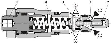
| ➀ | Main port 1 (P) |
| ➁ | Main port 2 (T) |
Type code
| 01 | 02 | 03 | 04 | 05 | 06 | 07 | 08 | 09 | |
| DBD | 4 | K | 1X | / | V | * |
| 01 | Pressure relief valve, direct controlled | DBD |
| Adjustment type for pressure adjustment | ||
| 02 | Grub screw with internal hexagon | S |
| Hand wheel | H | |
| 03 | Size 4 | 4 |
| 04 | Cartridge valve | K |
| 05 | Component series 10 ... 19 (10 ... 19: unchanged installation and connection dimensions) | 1X |
| Pressure rating | ||
| 06 | Set pressure up to 25 bar | 25 |
| Set pressure up to 50 bar | 50 | |
| Set pressure up to 100 bar | 100 | |
| Set pressure up to 200 bar | 200 | |
| Set pressure up to 315 bar | 315 | |
| Set pressure up to 350 bar | 350 | |
| Set pressure up to 420 bar | 420 | |
| Set pressure up to 500 bar | 500 | |
| Seal material (observe compatibility of seals with hydraulic fluid used, see "Technical data") | ||
| 07 | FKM seals | V |
| Type-examination procedure | ||
| 08 | Without type-examination procedure | no code |
| Type-examination tested safety valve according to Pressure Equipment Directive 2014/68/EU | E | |
| 09 | Further details in the plain text | * |
Type-examination tested safety valves, version "E"
(Component series 1X, according to the Pressure Equipment Directive 2014/68/EU)
| NG | Designation | Component marking | Maximum flow in l/min | Set response pressure in bar |
| 4 |  | TÜV.SV.- ■ -1038.4.F.G.p | 10 | 60 … 315 |
 | 17 | 320 … 500 |
| ■ Information is entered at the factory | |
| ▢ Pressure in the designation is to be entered by the customer, pressure adjustment ≥60 bar and possible in 5 bar steps. |
Technical data
general
| Weight (approx.) | kg | 0.3 |
| Installation position | any | |
| Ambient temperature range | °C | -20 … +80 |
hydraulic
| Maximum operating pressure | Inlet | bar | 500 |
| Outlet 1) | bar | 315 | |
| Hydraulic fluid | see table "Hydraulic fluid" | ||
| Hydraulic fluid temperature range | °C | -20 … +80 | |
| Viscosity range | mm²/s | 10 … 800 | |
| Maximum admissible degree of contamination of the hydraulic fluid, cleanliness class according to ISO 4406 (c) 2) | Class 20/18/15 | ||
| Maximum set pressure | bar | 25 50 100 200 315 350 420 500 | |
| Maximum flow | l/min | 20 |
| 1) | 50 bar with set pressure 500 bar |
| 2) | The cleanliness classes specified for the components must be adhered to in hydraulic systems. Effective filtration prevents faults and simultaneously increases the life cycle of the components. |
| Hydraulic fluid | Classification | Suitable sealing materials | Standards | Data sheet | |
| Mineral oils | HL, HLP | NBR, FKM | DIN 51524 | 90220 | |
| Bio-degradable | Insoluble in water | HETG | FKM | ISO 15380 | 90221 |
| HEES | FKM | ||||
| Soluble in water | HEPG | FKM | ISO 15380 | ||
| Important notes on hydraulic fluids:
| |||||
Deviating technical data : Type-examination tested safety valves, version "E"
(Component series 1X, according to the Pressure Equipment Directive 2014/68/EU)
general
| Ambient temperature range | °C | -10 … +60 |
| Conformity | CE according to Pressure Equipment Directive 2014/68/EU |
hydraulic
| Set response pressure | see last figure of the component marking | |
| Maximum counter pressure in the discharge line | See characteristic curves "Counter pressure in the discharge line” | |
| Hydraulic fluid | Hydraulic fluids according to DIN 51524: Hydraulic oils HL and HLP are suitable for safety valves with FKM seals. | |
| Hydraulic fluid temperature range (= "TS") | °C | -10 … +60 |
| Viscosity range | mm²/s | 12 … 230 |
| Maximum flow | The last but one figure of the component marking attached at the safety valve is always binding. For valve types which have a variable maximum flow depending on the response pressure, the discharge coefficient is specified at this place. | |
(For applications outside these values, please consult us!)
Diagrams/characteristic curves
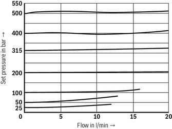
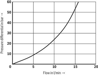
(measured with HLP46, ϑOil = 40 ±5 °C)
pE-qV characteristic curve
Δp-qV characteristic curves
Notices:
- The characteristic curves apply to an output pressure pT =0 bar in the entire flow range.
- he characteristic curves were measured without housing resistance.
Counter pressure in the discharge line
Basically, the valve should be operated without counter pressure in the discharge line, if possible. With counter pressure in the discharge line, the maximum flow possible is reduced. There is a relation between the maximum counter pressure pT in the discharge line and flow qV, which can be seen from the following characteristic curves. Characteristic curves for intermediate values of the response pressure which are not listed must be determined by means of interpolation.
With a flow approaching zero, the maximum counter pressure pT is in each case 10 % of the response pressure. With increasing flow, the maximum counter pressure pT is reduced.
Interpolation of intermediate values from the diagram
- At the axis pT , mark 1/10 of the value of pA.
- Determine the next lower and the next higher characteristic curve for this point. The point marked at pT divides the section between lower and higher characteristic curve on the pT axis with a certain percentage.
- At the qV max axis, divide the section between next lower and next higher characteristic curve in the same percentage as the section at the pT axis. From the zero position flow on the qV max axis determined in that way, draw a straight line to the value on the pT axis marked before.
- Mark the system flow to be secured at the qV max axis
- Read off the maximum counter pressure for this value using the line at the pT axis drawn before.
Determination of the maximum counter pressure
Example:
- Flow of the system / accumulator to be secured : qVmax = 5 l/min
- Safety valve set to : pA = 500 bar
- Read off the maximum counter pressure pT of approx. 36 bar from the diagram (see arrows, characteristic curve 7).
Diagram for determining the maximum counter pressure pT in the discharge line at port T of the valve dependent on the flow qVmax with different response pressures pA.Intermediate values may be determined by means of interpolation. Regarding the procedure for interpolation refer to "Interpolation of intermediate values from the diagram".
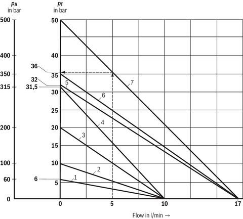
| Characteristic curves | Response pressurepA in bar |
| 1 | 60 |
| 2 | 100 |
| 3 | 200 |
| 4 | 315 |
| 5 | 320 |
| 6 | 350 |
| 7 | 500 |
| pA | Response pressure in bar |
| pT | Maximum counter pressure in the discharge line (port T) in bar |
| qVmax | Maximum flow in l/min |
Symbols/Circuit diagrams

Dimensions
Dimensions in mm
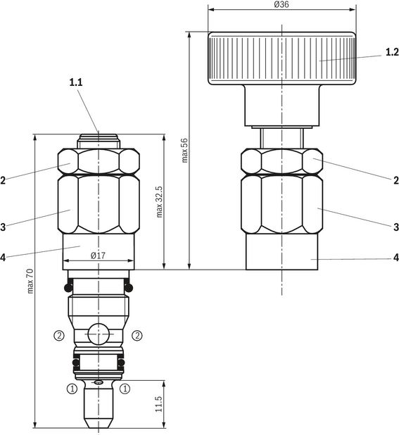
| 1.1 | Adjustment type “S”, internal hexagon SW5 |
| 1.2 | Adjustment type “H”, hand wheel |
| 2 | Lock nut SW17, tightening torque MA = 10+5 Nm |
| 3 | Hexagon SW17, tightening torque during screw-in MA = 23±2 Nm |
| 4 | Embossed type designation |
|
| |
| ➀ | Main port 1 (P) |
| ➁ | Main port 2 (T) |
Mounting cavity: R/DBD . 4K; 2 main ports; thread M14 x 1
Dimensions in mm
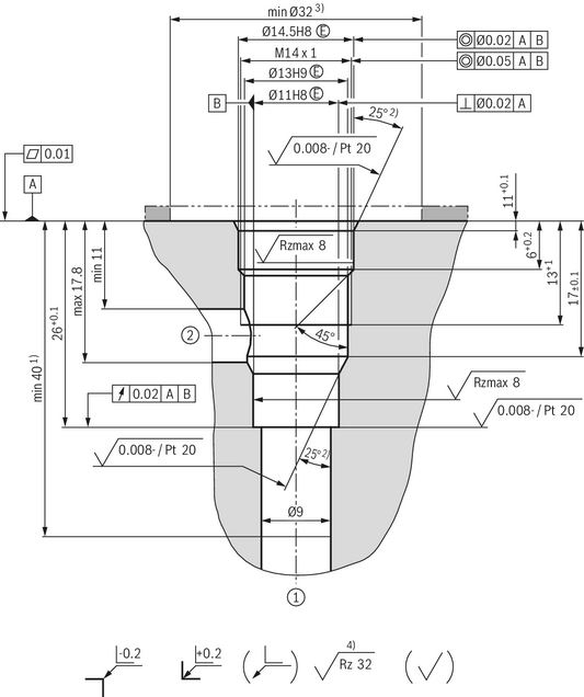
| 1) | Depth for moving parts |
| 2) | All seal ring insertion faces are rounded and free of burrs |
| 3) | With countersink |
| 4) | Visual inspection |
|
| |
| ➀ | Main port 1 (P) |
| ➁ | Main port 2 (T), can optionally be arranged at the circumference |
| Tolerance for all angles ±0.5° | |
Information
General information
Hydraulic counter pressures in the main port ② (T) add 1:1 to the response pressure of the valve set at the adjustment.
Example:
Pressure adjustment of the valve due to spring preload (item 4 "Product description"): pspring = 200 bar
Hydraulic counter pressure in the main port ② (T): phydraulic = 50 bar
=> Response pressure = pspring + phydraulic = 250 bar
Safety Instructions
Type-examination tested safety valves, version "E"
(Component series 1X, according to the Pressure Equipment Directive 2014/68/EU)
The functionality of these valves corresponds to that of the standard series (see "Product description"). Valves of type DBD…E are, however, type-examination tested pressure relief valves according to the Pressure Equipment Directive 2014/68/EU and intended for use as safety valves.
At the factory, the response pressure is set to a fixed maximum value using the adjustment type. Afterwards, the safety valve is sealed and/or secured using a safety cap which cannot be disassembled in non-destructive manner.
The safety valves are available with graded response pressures (in 5 bar steps). The valve version provided with a safety cap can no longer be adjusted. With valve versions equipped with rotary knob or hand wheel, the valve spring can be unloaded by the user. This way, a response pressure lower than the factory setting can be set without the need of removing the lead seal.
- Before ordering a type-examination tested safety valve, it must be observed that for the desired response pressure p, the maximum admissible flowqVmax of the safety valve must be larger than the maximum possible flow of the system/accumulator to be secured. According to the Pressure Equipment Directive 2014/68/EU, the increase in the system pressure due to the flow must not exceed 10 % of the set response pressure (see component marking - ordering code, type-examination tested safety valves).
- The maximum admissible flow qVmax stated in the component marking must not be exceeded.
- Discharge lines of safety valves must end in a risk-free manner. The accumulation of fluids in the discharge system must not be possible (see data sheet AD2000 A2).
Always observe application notes:
- In the plant, the response pressure specified in the component marking is set with a flow of 1 l/min.
- The maximum flow stated in the component marking applies for applications without counter pressure in the discharge line (port T).
- By removing the lead seal at the safety valve, the approval according to the Pressure Equipment Directive becomes void.
- The requirements of the Pressure Equipment Directive and of data sheet AD2000 A2 must be observed.
- It is recommended to secure type-examination tested safety valves against inadmissible disassembly by means of wiring and sealing with the housing/block (bore available in the adjustment type).
Notice:
The system pressure increases by the counter pressure in the discharge line (port T) due to the increasing flow. (Observe the data sheet AD 2000 A 2, point 6.3!)
To ensure that this increase in system pressure caused by the flow does not exceed the value of 10% of the set response pressure, the admissible flow has to be reduced dependent on the counter pressure in the discharge line (port T) (see diagrams - Safety instructions, Type-examination tested safety valves).
Downloads


Цена по запросу
Нет отзывов об этом товаре.