
Артикул: RX7554
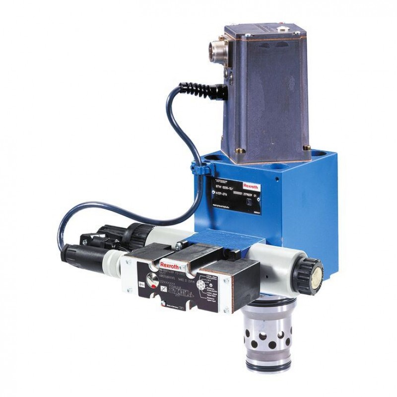
Directional high-response cartridge valve, pilot-operated, with integrated electronics (OBE) 2WRCE...-2X/P
Доступно к заказу
Цена по запросу
И выбери подходящего.
Description
- Size 32 … 50
- Component series 2X
- Maximum operating pressure 420 bar
- Maximum flow 4500 l/min
Features
- 2/2-directional cartridge valve
- Pilot control valve: proportional directional valve
- Main stage with position control
- Normalized:
- Installation dimensions according to ISO 7368 - Flexible:
– Suitable for position, pressure, force and velocity control - Typical applications:
- Presses
- Die casting machines
- Nibbling axes
Product description
Valves of type 2WRCE are pilot-operated, 2-stage directional high-response cartridge valves. They control the quantity and direction of a flow and are mainly used in control loops.
Set-up
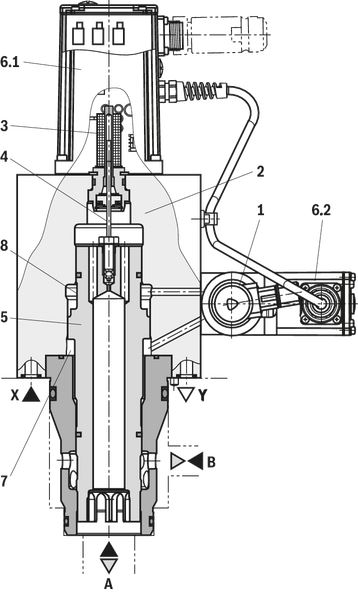
The valves consist of the following assemblies:
- 1-stage pilot control valve (1)
- with two solenoids as electro-mechanical converters and a control spool that is connected to the integrated pilot electronics (6.2) via electrical feedback
- Second stage (2) for flow control
- An inductive position transducer (3) the core (4) of which is attached to the main control spool (5) of the second stage
- Integrated electronics (OBE) (6.1).
Function
The integrated electronics (OBE) compares command and actual values and the solenoids of the pilot control valve (1) are actuated with a proportional current according to the control deviation.
The pilot control valve (1) takes a proportionally controlled position and controls the flow in and out of the control chambers A (7) and B (8) that actuate the main control spool (5) through the closed valve control loop up to 0 control deviation.
This means that the stroke of the main control spool (5) is regulated proportionally to the command value. It must be noted that the flow also depends on the valve pressure drop.
Valve features
The flow can pass through the valve from A to B or from B to A.
The control spool (seat design) closes or opens at 5% of the command value. At lower command values, the valve control loop attempts to guide the control spool, thus presses it onto the seat at full pilot pressure and blocks the connection in a leakage-free way.
The specified valve dynamics only apply to the control area of the valve. At command value steps from the seat to lower opening values, additional delay times occur.
The opening point of 5% (= 0.5 V or 0.5 mA) is set at the factory.
Due to the internal setting of the pilot control valve, the pilot pressure is connected to control chamber B (8) in case of a power failure, i.e. the main stage is closed.
The control electronics feature an offset setting to compensate pilot trimming.
Due to differences in diameter in the seat range, the control spools are statically not pressure-compensated. To compensate the force differential, 6% of the system pressure is required for version "L" and 22% of the system pressure is required for version "R" as pilot pressure. With reserves for flow force and dynamics, this defines the recommended minimum pilot pressure.
Notice:
Preferably, port B is to be connected to the actuator.
Type code
| 01 | 02 | 03 | 04 | 05 | 06 | 07 | 08 | 09 | 10 | 11 | 12 | 13 | 14 | |||
| 2 | WRCE | S | ‒ | 2X | / | P | G24 | K31 | / | * |
| 01 | 2 main ports | 2 |
| 02 | Directional high-response cartridge valve, pilot-operated, with integrated electronics (OBE) | WRCE |
| 03 | Size 32 | 32 |
| Size 40 | 40 | |
| Size 50 | 50 | |
| 04 | Control spool in seat design | S |
| Rated flow (Δp = 5 bar) | ||
| 05 | Size 32 | |
| 480 l/min 1) | 480 | |
| 650 l/min 2) | 650 | |
| Size 40 | ||
| 700 l/min 1) | 700 | |
| 1000 l/min 2) | 1000 | |
| Size 50 | ||
| 1100 l/min 1) | 1100 | |
| 1600 l/min 2) | 1600 | |
| Flow characteristic | ||
| 06 | Linear | L |
| Linear with progressive fine control range | R | |
| 07 | Component series 20 ... 29 (20 ... 29: unchanged installation and connection dimensions) - Size 6 | 2X |
| Pilot control valve | ||
| 08 | Proportional directional valve | P |
| Power supply | ||
| 09 | Direct voltage 24 V | G24 |
| Electrical connection | ||
| 10 | Without mating connector, connector according to DIN EN 175201-804 | K31 3) |
| Electrical interface | ||
| 11 | Command value 0 ...+10 V, actual value 0.5 ...+10 V | A1 |
| Command value 0 ...+10 mA, actual value 0.5 ...+10 mA | C1 | |
| Sandwich plate shut-off valve | ||
| 12 | Without shut-off valve | no code |
| With shut-off valve | ||
| De-energized shut-off valve actively closes “2WRCE” with applied pilot pressure | WK15 | |
| De-energized shut-off valve actively opens “2WRCE” with applied pilot pressure | WL15 | |
| Seal material (observe compatibility of seals with hydraulic fluid used, see "Technical data") | ||
| 13 | NBR seals | M |
| FKM seals | V | |
| 14 | Further details in the plain text | * |
| 1) | Only version "R" |
| 2) | Only version "L" |
| 3) | Mating connectors, separate order, see "Accessories" and datasheet 08006. |
Technical data
general
| Size | 32 | 40 | 50 | ||
| Component series | 2X | ||||
| Installation position; commissioning | any, preferably horizontal | ||||
| Storage temperature range | °C | -20 … +80 | |||
| Ambient temperature range | °C | -20 … +50 | |||
| Earth | Without shut-off valve | kg | 12.5 | 19.9 | 26.8 |
| With shut-off valve | kg | 13.7 | 21.1 | 28 | |
| Sine test according to DIN EN 60068-2-6 | 5 ... 2000 Hz / maximum of 10 g / 10 cycles | ||||
| Noise test according to DIN EN 60068-2-64 | 20 ... 2000 Hz / 10 gRMS / 30 min | ||||
| Transport shock according to DIN EN 60068-2-27 | 15 g / 11 ms | ||||
hydraulic
| Size | 32 | 40 | 50 | |||
| Maximum operating pressure | Main stage | Anschluss A | bar | 420 | ||
| Port B | bar | 420 | ||||
| Pilot control valve | Port X | bar | 315 | |||
| Port Y | bar | 210 | ||||
| Minimum pilot pressure 1) | Version “L” | % | 15 | |||
| Version “R” | % | 45 | ||||
| Nominal flow 2) | Version “L” | l/min | 650 | 1000 | 1600 | |
| Version “R” | l/min | 480 | 700 | 1100 | ||
| Maximum flow | Version “L” | l/min | 1500 | 2200 | 3500 | |
| Version “R” | l/min | 2000 | 3000 | 4500 | ||
| Pilot flow 3) | l/min | 37 | 45 | 60 | ||
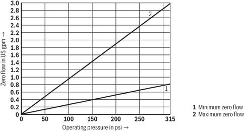
| Zero flow | Pilot control valve | See characteristic curves | ||||
| Control flow | cm³ | 4.52 | 8.48 | 17.3 | ||
| Hydraulic fluid | see table "Hydraulic fluid" | |||||
| Hydraulic fluid temperature range | Maximum admissible | °C | -20 … +80 | |||
| Recommended | °C | +40 … +50 | ||||
| Viscosity range | Maximum admissible | mm²/s | 20 … 380 | |||
| Recommended | mm²/s | 30 … 45 | ||||
| Maximum admissible degree of contamination of the hydraulic fluid, cleanliness class according to ISO 4406 (c) 4) | Class 20/18/15 | |||||
| Hysteresis | % | ≤ 0.2 | ||||
| Range of inversion | % | ≤ 0.1 | ||||
| Response sensitivity | % | ≤ 0.1 | ||||
| Closing time 5) | Pilot control valve | ms | ≤ 200 | |||
| With shut-off valve | ms | ≤ 200 | ||||
| 1) | In % of the system pressure |
| 2) | qVnom +10 %; ∆p = 5 bar |
| 3) | Stepped input signal (seat position at 100%, pilot pressure 315 bar) |
| 4) | The cleanliness classes specified for the components must be adhered to in hydraulic systems. Effective filtration prevents faults and simultaneously increases the life cycle of the components. For the selection of the filters, see www.boschrexroth.com/filter. |
| 5) | With pilot pressures from 40 bar … 315 bar |
| Hydraulic fluid | Classification | Suitable sealing materials | Standards | Data sheet | |
| Mineral oils | HL, HLP, HLPD, HVLP, HVLPD | NBR, FKM | DIN 51524 | 90220 | |
| Bio-degradable | Insoluble in water | HETG | NBR, FKM | ISO 15380 | 90221 |
| HEES | FKM | ||||
| Soluble in water | HEPG | FKM | ISO 15380 | ||
| Flame-resistant | Water-free | HFDU (glycol base) | FKM | ISO 12922 | 90222 |
| HFDU (ester base) | FKM | ||||
| HFDR | FKM | ||||
| Containing water | HFC (Fuchs: Hydrotherm 46M, Renosafe 500; | NBR | ISO 12922 | 90223 | |
| Important information on hydraulic fluids:
| |||||
electrical
| Voltage type | Direct voltage | ||
| Type of signal | analog | ||
| Protection class according to DIN EN 60529 | IP65 (If a suitable and a correctly mounted mating connector are used.) | ||
| Zero point calibration | % | ≤ 1 | |
| Zero shift upon change of | Hydraulic fluid temperature | %/10 K | ≤ 0.3 |
| Pilot pressure | %/100 bar | ≤ 0.7 | |
| Return flow pressure | %/bar | ≤ 0.3 | |
Notice:
For information on the environment simulation testing for the areas EMC (electromagnetic compatibility), climate and mechanical load see data sheet 29137-U (declarations on environmental compatibility).
Diagrams/characteristic curves
(measured with HLP32, ϑOil = 40 ±5 °C)
Zero flow at the pilot control valve
Size 32
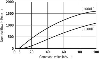
Nominal flow
(Δp = 5 bar; A → B, B → A)

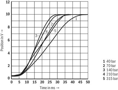
Transition function

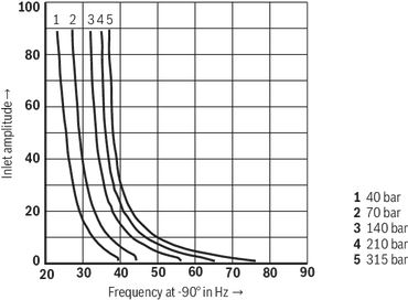
Frequency response
(pP = 315 bar)
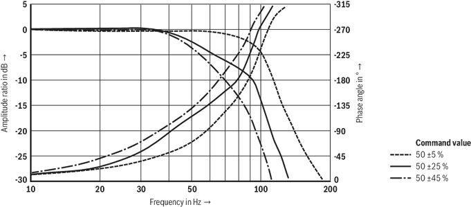
Frequency f dependent on operating pressure and inlet amplitude
Size 40
Nominal flow
(Δp = 5 bar; A → B, B → A)

Transition function

Frequency response
(pP = 315 bar)

Frequency f dependent on operating pressure and inlet amplitude

Size 50
Nominal flow
(Δp = 5 bar; A → B, B → A)
Transition function
Frequency response
(pP = 315 bar)

Frequency f dependent on operating pressure and inlet amplitude

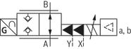
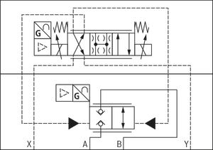
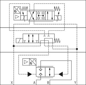
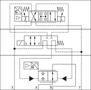
Symbols/Circuit diagrams
Simplified
"No code" and "WK15" version
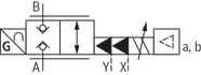
Version "WL15"
Detailed
Version "no code"
Version "WK15"
Version "WL15"
Notice:
Representation according to DIN ISO 1219-1.
Electrical connection
Connector pin assignment
| Pin | Signal | Interface | |
| "A1" | "C1" | ||
| A | Power supply | 24 VDC nominal (18 ... 30 V; Iaverage = 1A, Ipeak = 3 A) | |
| B | 0 VDC | ||
| C | Measurement zero | Reference to pin F | |
| D | Differential command value input | 0 to +10 V Input resistance > 100 kΩ | 0 ... +10 mA; load resistance 100 Ω |
| E | |||
| F | Actual value Reference is pin C | +0,5 … +10 V; maximum 10 mA | +0.5 ... +10 mA; load resistance maximum 1 kΩ |
| PE | Functional ground (directly connected to valve housing) | ||
Notices:
- Do not connect PE if the valve has already been grounded via the system.
- Command value and actual value have the same polarity. In case of failure of the fuse “1A fast”, the actual value may temporarily also be measured between F and B.
- Electrical signals provided via control electronics (e.g. actual value) must not be used to switch off safety-relevant machine functions.
- Mating connectors, separate order, see "Accessories" and datasheet 08006.
Nominal command value range
0 … +10 V; 0 … +10 mA (0 … 100 %)
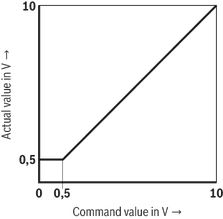
- In case of a slow command value modification from 0.5 V ... +10 V, the actual value follows the command value within ±0.15 V.
- With command values of more than +10 V, the actual value will follow to approx. +12 V
- In the command value range of 0 … +0.5 V, the actual value remains constant at 0.5 V.
- At a command value step to +10 V, the actual value can temporarily reach values of up to approx. +10.5 V.
Block diagram / controller function block
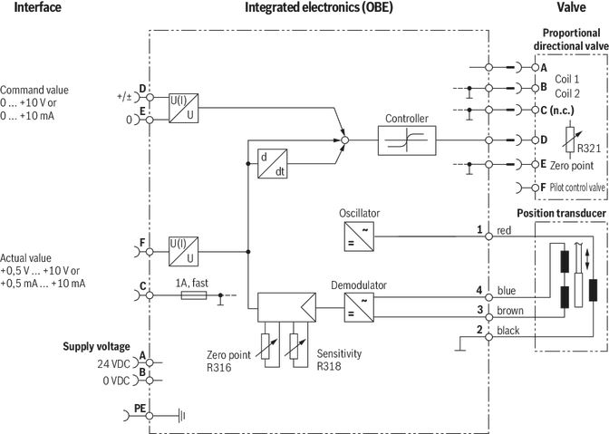
Effect of the control:
- A positive signal at pin D and a reference potential at pin E results in flow A → B or B → A
- A positive signal at pin F and a reference potential at pin C results in flow A → B or B → A
Dimensions
Size 32
Dimensions in mm
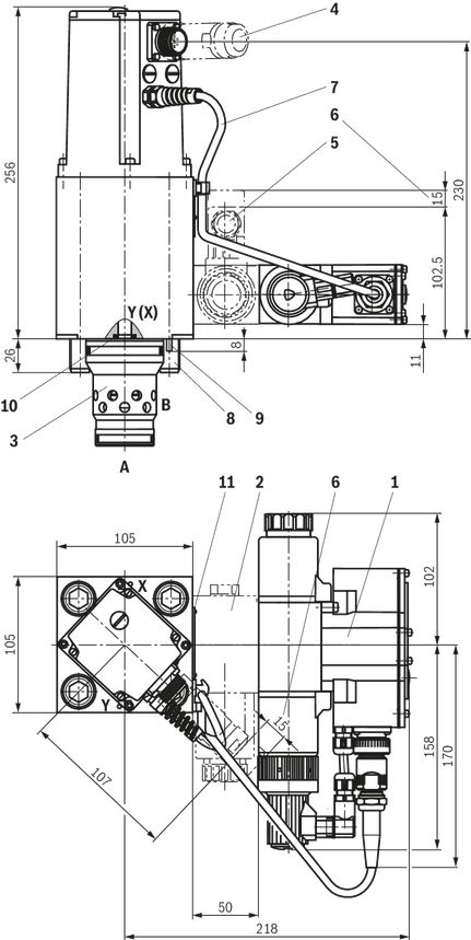
| 1 | Pilot control valve (proportional directional valve NG6) |
| 2 | Sandwich plate shut-off valve (only with versions “WK15” and “WL15”) |
| 3 | Socket |
| 4 | Mating connectors for valves with round connector, 6-pole, separate order, see "Accessories" |
| 5 | Mating connectors for valves with connector "K4", separate order, see "Accessories" |
| 6 | Space required to remove the mating connector |
| 7 | Cabling |
| 8 | Valve mounting screws (included in the scope of delivery) (see below) |
| 9 | Locking pin |
| 10 | Identical seal rings for ports X and Y |
| 11 | Name plate |
Size 40
Dimensions in mm
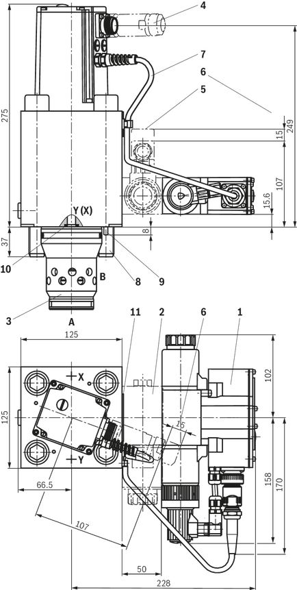
| 1 | Pilot control valve (proportional directional valve NG6) |
| 2 | Sandwich plate shut-off valve (only with versions “WK15” and “WL15”) |
| 3 | Socket |
| 4 | Mating connectors for valves with round connector, 6-pole, separate order, see "Accessories" |
| 5 | Mating connectors for valves with connector "K4", separate order, see "Accessories" |
| 6 | Space required to remove the mating connector |
| 7 | Cabling |
| 8 | Valve mounting screws (included in the scope of delivery) (see below) |
| 9 | Locking pin |
| 10 | Identical seal rings for ports X and Y |
| 11 | Name plate |
Size 50
Dimensions in mm
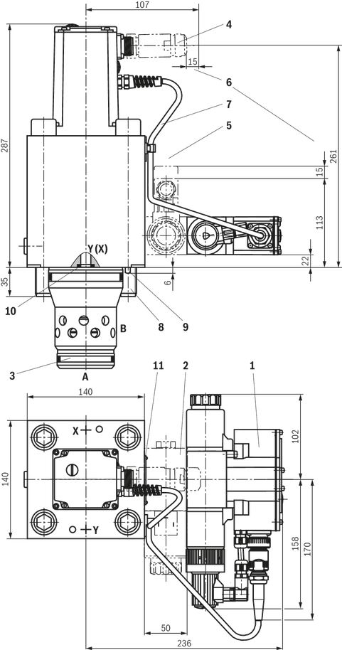
| 1 | Pilot control valve (proportional directional valve NG6) |
| 2 | Sandwich plate shut-off valve (only with versions “WK15” and “WL15”) |
| 3 | Socket |
| 4 | Mating connectors for valves with round connector, 6-pole, separate order, see "Accessories" |
| 5 | Mating connectors for valves with connector "K4", separate order, see "Accessories" |
| 6 | Space required to remove the mating connector |
| 7 | Cabling |
| 8 | Valve mounting screws (included in the scope of delivery) (see below) |
| 9 | Locking pin |
| 10 | Identical seal rings for ports X and Y |
| 11 | Name plate |
Notice:
The dimensions are nominal dimensions which are subject to tolerances.
Valve mounting screws (included in the scope of delivery)
| Size | Quantity | Hexagon socket head cap screws |
| 32 | 4 | ISO 4762 - M16 x 100 - 10.9-flZn/nc/480h/C Tightening torque MA = 250 Nm ±10 % |
| 40 | 4 | ISO 4762 - M20 x 180 -10.9 Tightening torque MA = 590 Nm ±10 % |
| 50 | 4 | ISO 4762 - M20 x 190 -10.9 Tightening torque MA = 590 Nm ±10 % |
| Notice: For tightening, use a manual torque wrench with a tolerance ≤10 %. | ||
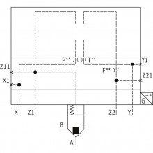
Installation bore
Dimensions in mm
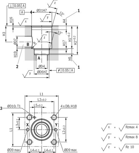
| 1 | Depth of fit, minimum dimension |
| 2 | The ports P, T and B can be positioned around the central axis of port A. However, it must be observed that the mounting bores and the control bores are not damaged. |
| 3 | Bore for locating pin |
| NG | 32 | 40 | 50 | |
| ØD1H7 | mm | 60 | 75 | 90 |
| ØD2H7 | mm | 58 | 73 | 87 |
| ØD3H7 | mm | 55 | 55 | 68 |
| ØD4 | mm | 32 | 40 | 50 |
| ØD5 | mm | 24 | 30 | 35 |
| ØD6H7 | mm | 45 | 55 | 68 |
| ØD7 | mm | 32 | 40 | 50 |
| D8 | M16 | M20 | M20 | |
| ØD9 max | mm | 8 | 10 | 10 |
| ØD10 | mm | 6 | 6 | 8 |
| H1 | mm | 70 | 87 | 100 |
| H2 | mm | 85 | 105 | 122 |
| H3 | mm | 52 | 64 | 72 |
| H4 | mm | 30 | 30 | 35 |
| H5 | mm | 13 | 15 | 17 |
| H7 | mm | 43.5 | 54 | 87 |
| H8 | mm | 85 | 105 | 143 |
| H9 | mm | 100 | 125 | 165 |
| H10 | mm | 30 | 36 | 66 |
| H11 | mm | 70.5 | 87 | 122 |
| H12 | mm | 18 | 21 | 48 |
| H13 | mm | 15 | 18 | 18 |
| H16 | mm | 2.5 | 3 | 4 |
| H17 | mm | 2.5 | 3 | 3 |
| H18 | mm | 35 | 45 | 45 |
| H19 | mm | 2 | 3 | 3 |
| H20 | mm | 2.5 | 3 | 3.5 |
| H21 | mm | 1.5 | 3 | 3.5 |
| L1 | mm | 105 | 125 | 140 |
| L2 | mm | 70 | 85 | 100 |
| L3 | mm | 35 | 42.5 | 50 |
| L4 | mm | 41 | 50 | 58 |
| L5 | mm | 17 | 23 | 30 |
| T1 | mm | 10 | 10 | 10 |
Notice:
Tolerances according to: General tolerances ISO 2768-mK
Accessories
Mating connectors for valves with connector “K4”, without circuitry, standard
3P Z4
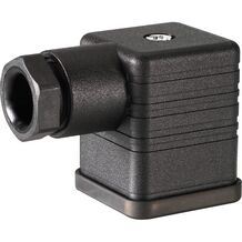
Mating connectors for valves with connector “K4”, without circuitry, standard
3P Z4
- For valves with connector “K4” according to EN 175301-803 and ISO 4400, 2-pole + PE, “large cubic connector”
- Mating connectors for valves with one or two solenoids (individual connection)
Mating connectors for valves with connector “K4”, with indicator light
3P Z5L
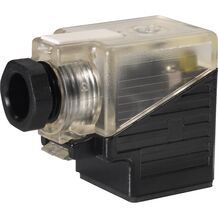
Mating connectors for valves with connector “K4”, with indicator light
3P Z5L
- For valves with connector “K4” according to EN 175301-803 and ISO 4400, 2-pole + PE, “large cubic connector”
- Mating connectors for valves with one or two solenoids (individual connection)
Mating connectors for valves with connector “K4”, with indicator light and Zener diode suppression circuit
3P Z5L1
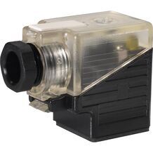
Mating connectors for valves with connector “K4”, with indicator light and Zener diode suppression circuit
3P Z5L1
- For valves with connector “K4” according to EN 175301-803 and ISO 4400, 2-pole + PE, “large cubic connector”
- Mating connectors for valves with one or two solenoids (individual connection)
Mating connectors for valves with connector “K4”, with rectifier
3P RZ5
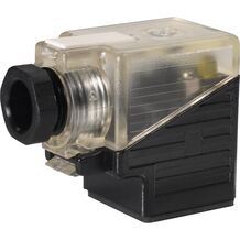
Mating connectors for valves with connector “K4”, with rectifier
3P RZ5
- For valves with connector “K4” according to EN 175301-803 and ISO 4400, 2-pole + PE, “large cubic connector”
- Mating connectors for valves with one or two solenoids (individual connection)
Mating connectors for valves with round connector, 6-pole + PE
7P Z31
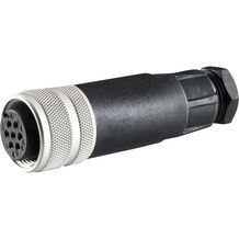
Mating connectors for valves with round connector, 6-pole + PE
7P Z31
- For valves with round connector according to EN 175201-804, 6-pole + PE as well as 6-pole, compatible with VG 95328
Downloads
 | Directional high-response cartridge valve, pilot-operated, with integrated electronics (OBE) Data Sheet | RE29137 | 2019-04-01 | English | PDF | 1.2MB Product Groups: Proportional flow control valves Type WRCE |

Цена по запросу
Цена по запросу

Цена по запросу
Цена по запросу
Цена по запросу
Цена по запросу
Нет отзывов об этом товаре.