
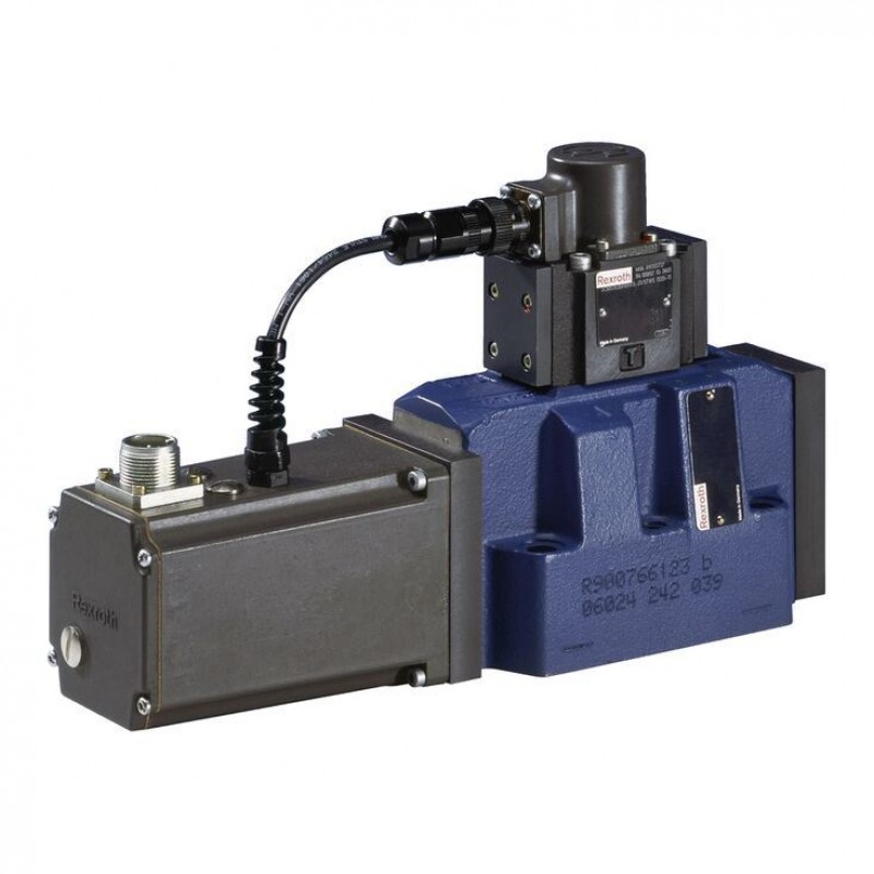
Доступно к заказу
Цена по запросу
И выбери подходящего.
Description
- Size 16
- Component series 2X
- Maximum operating pressure 350 bar
- Maximum flow 570 l/min
Features
- Valve to control position, force, pressure or velocity
- 3-stage servo valve with electrical position control of the control spool of the 3rd stage, position sensing of the control spool by means of an inductive position transducer
- 2-stage pilot control valve of size 6 with high dynamics
- 1st stage nozzle/flapper plate amplifier
- Filter for 1st stage freely accessible and replaceable from the outside
- For subplate mounting: Porting pattern according to ISO 4401
- Can also be used as 3-way version
- Valve and integrated control electronics are adjusted and tested
- Optimized valve control loop
- High response sensitivity, very low hysteresis and zero point drift
- Internal or external pilot oil supply and pilot oil return available
- Gap seals at pressure chambers of the control sleeve, no O-ring wear
Product description
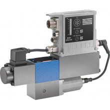
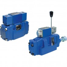
Valves of type 4WSE3E... are electrically operated, 3-stage directional servo valves. They are mainly used to control position, force or pressure and velocity.
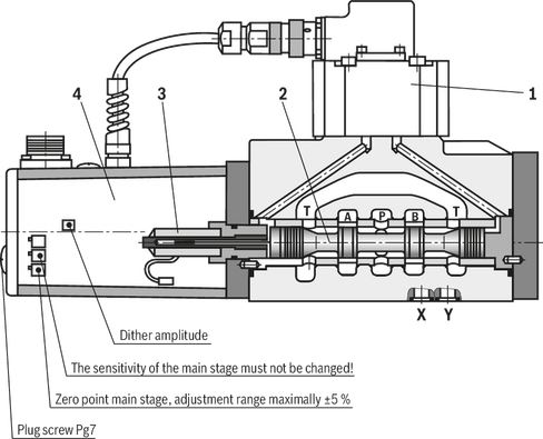
These valves consist of a 2-stage pilot control valve of type 4WS2EM 6 (1), a main stage with a main control spool in a sleeve (2), an inductive position transducer (3), and the integrated control electronics (4).
The pilot control valve (1) consists of an electro-mechanical converter (torque motor), a hydraulic amplifier (nozzle flapper plate principle) and a pilot spool in a sleeve, which is connected to the torque motor via a mechanical feedback.
Electric currents in the coils of the torque motor generate a force by means of a permanent magnet which acts on the armature, and in connection with a torque tube results in a torque. This causes the flapper plate which is connected to the torque tube via a bolt to move from the central position between the two control nozzles, and a pressure differential is created across the front sides of the pilot control spool. The pressure differential results in the control spool changing its position, which results in the pressure port being connected to one actuator port and, at the same time, the other actuator port being connected to the return flow port.
The pilot control spool is connected to the flapper plate or the torque motor by means of a bending spring (mechanical feedback). The position of the control spool is changed until the flapper plate position and hence the pressure differential across the nozzle flapper plate system becomes zero due to the feedback torque, which acts via the bending spring against the electro-magnetic torque of the torque motor.
In doing so, the stroke of the pilot control spool and hence the flow of the pilot control valve is controlled proportionally to the electrical input signal.
In the main stage, the main control spool (2) is operated by the pilot control valve and its position is sensed by an inductive position transducer (3). The position transducer signal is compared to the command value by integrated control electronics (4). Any possible control deviation is amplified electrically and fed to the pilot control valve as control signal. The pilot control valve starts to move and the main control spool is re-positioned.
The stroke of the main control spool and consequently the flow of the servo valve are controlled proportionally to the command value. It must be noted that the flow depends on the valve pressure differential.
The valve zero point can be adjusted by means of an externally accessible potentiometer.
The valves are set at the factory with a dither default setting with the constant frequency of 400 Hz.
Notice!
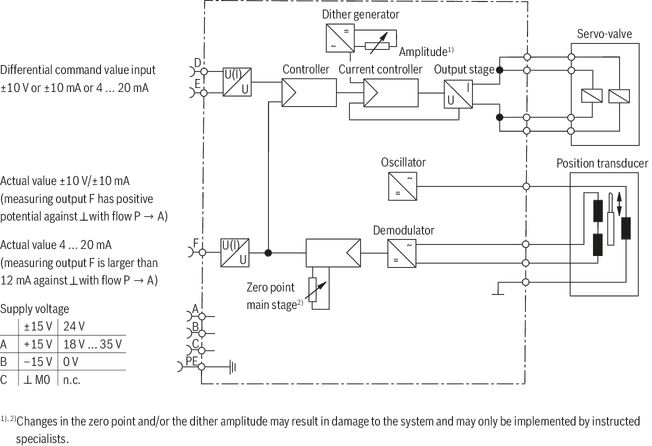
Changes in the zero point and/or the dither amplitude may result in damage to the system and may only be implemented by instructed specialists.
The pilot control valve may only be maintained by Bosch Rexroth employees. An exception to this is the replacement of the filter element.
Type code
| 01 | 02 | 03 | 04 | 05 | 06 | 07 | 08 | 09 | 10 | 11 | 12 | 13 | 14 | |||
| 4WSE3E | 16 | - | 2X | / | / | K31 | * |
| 01 | 3-stage servo valve | 4WSE3E |
| 02 | Size 16 | 16 |
| 03 | Symbols; for the possible version, see "Symbols/Circuit diagrams" | V, V1 |
| Control spool position in de-energized state | ||
| 04 | Not defined | no code |
| 100 % P→A / B→T | P | |
| Rated flow at 70 bar valve pressure differential | ||
| 05 | 105 l/min | 100 |
| 150 l/min | 150 | |
| 200 l/min | 200 | |
| 260 l/min | 300 | |
| Control spool overlap | ||
| 06 | 0 ... 0,5 % positiv | D |
| 0 ... 0,5% negativ | E | |
| 07 | Component series 20 ... 29 (20 ... 29: unchanged installation and connection dimensions) - Size 6 | 2X |
| Seal material | ||
| 08 | FKM seals | V |
| NBR seals | M | |
| Pilot flow | ||
| 09 | External pilot oil supply, external pilot oil return | XY |
| External pilot oil supply, internal pilot oil return | XT | |
| Internal pilot oil supply, external pilot oil return | PY | |
| Pilot oil supply internal, pilot oil return internal | PT | |
| Pressure rating | ||
| 10 | 7 | |
| 315 bar | 9 | |
| Power supply | ||
| 11 | ±15 V | 15 |
| +24 V | 24 | |
| Electrical connection | ||
| 12 | 6+PE, ohne Leitungsdose | K31 |
| Electrical interface | ||
| 13 | 0 ... 10 V | A1 |
| 0 ... 10 mA | C1 | |
| 4 ... 20 mA | F1 1) | |
| 14 | Further details in the plain text | * |
| 1) | Only with +24V supply voltage | |
Technical data
general
| Type | 4WSE3E | |
| Size | 16 | |
| Component series | 2X | |
| Porting pattern | according to ISO 4401 | |
| Installation position | any - if it is ensured that the pilot control is supplied with sufficient pressure (> 10 bar) during start-up of the system. In case of insufficient pressure supply, the control spool of the servo valve can take any position. This may result in channel P being connected to the actuator and the pressure build-up being delayed. This may be prevented by providing an external pressure supply at port X. | |
| Storage temperature range | °C | -20 … +80 |
| Weight | kg | 9.5 |
| Ambient temperature range | °C | -20 … +60 |
hydraulic
| Type | 4WSE3E | |||
| Maximum operating pressure | bar | 350 | ||
| Maximum operating pressure | Anschluss A | Internal pilot oil | bar | 315 |
| Port B | Internal pilot oil | bar | 315 | |
| Port P | Internal pilot oil | bar | 315 | |
| Anschluss A | External pilot oil | bar | 350 | |
| Port B | External pilot oil | bar | 350 | |
| Port P | External pilot oil | bar | 350 | |
| Operating pressure range | Pilot control stage | Pilot oil supply | bar | 10 ... 210 bar bzw. 10 ... 315 bar (je nach Druckstufe) |
| Maximum return flow pressure | Port T | Pilot oil return, external | bar | 250 |
| Pilot oil return, internal | bar | Pressure peaks < 100, static < 10 | ||
| Port Y | bar | Pressure peaks < 100, static < 10 | ||
| Rated flows qv nom at 70 bar valve pressure differential (35 bar/control edge) 1) | l/min | 105 | ||
| Zero flow | See characteristic curves | |||
| Hydraulic fluid | see table | |||
| Hydraulic fluid temperature range | °C | -20 … +80 | ||
| preferably | °C | +40 … +50 | ||
| Hysteresis (dither-optimized) | % | ≤ 0.1 | ||
| Range of inversion (dither-optimized) | % | ≤ 0.05 | ||
| Response sensitivity (dither-optimized) | % | ≤ 0.05 | ||
| Pressure amplification 2) | % | ≥ 90 | ||
| Zero shift upon change of | Hydraulic fluid temperature | %/10 K | ≤ 0.3 | |
| Ambient temperature | %/10 K | ≤ 0.3 | ||
| Operating pressure 80 … 120 % of pP | %/100 bar | ≤ 0.3 | ||
| Return flow pressure 0 … 10 % of pP | %/100 bar | ≤ 0.3 | ||
| 1) | Tolerance ±10 % with valve pressure differential Δp = 70 bar |
| 2) | of pp with 1 % spool stroke change (from the hydraulic zero point) |
| Hydraulic fluid | Classification | Suitable sealing materials | Standards |
| Mineral oils and related hydrocarbons | HL, HLP | NBR / FKM | DIN 51524 |
| Flame-resistant - containing water | HFC
| NBR | ISO 12922 |
| Important information on hydraulic fluids: For more information and data on the use of other hydraulic fluids please contact us. There may be limitations regarding the technical valve data (temperature, pressure range, life cycle, maintenance intervals, etc.). Flame-resistant – containing water: | |||
electrical
| Type | 4WSE3E | |
| Size | 16 | |
| Protection class according to EN 60529 | IP65 (If a suitable and a correctly mounted mating connector are used.) | |
| Type of signal | analog | |
Diagrams/characteristic curves
(measured with HLP46, ϑOil = 40 ±5 °C)
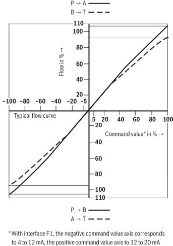
Flow/load function with maximum valve opening (tolerance ±10 %)
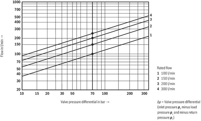
Summated edge Δpv = 70 bar
Single edge Δpv = 35 bar (tolerance ±5 %)
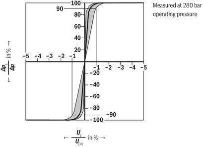
Pressure-signal characteristic curve
Zero flow, total, with “D” overlap (pilot control valve and main stage), tolerance ±20 %
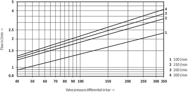
| Zero flow Data valid for overlap "E" | Pilot control valve L1 | l/min |  |
| Complete valve qV | l/min |  | |
| qvnom | Rated flow (complete valve) in l/min | 105, 150, 200, 260 | |
| pp | Operating pressure in bar | ||
| Δp | Valve pressure differential in bar | 70 | |
| qv | l/min | 100, 150, 200, 300 |
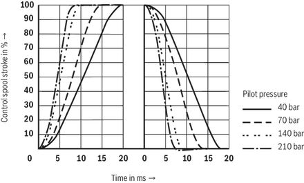
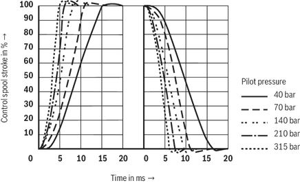
Transition function with pressure rating 210 bar
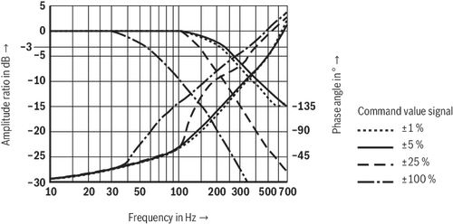
Frequency response with pp = 210 bar - measured with pressure rating 210 bar
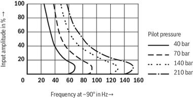
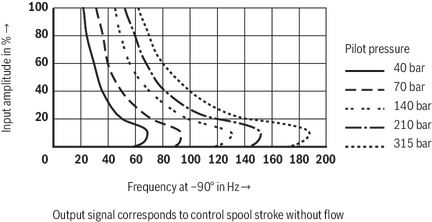
Dependency of the frequency f at -90° of the pilot pressure - measured with 210 bar pressure rating
Transition function with pressure rating 315 bar
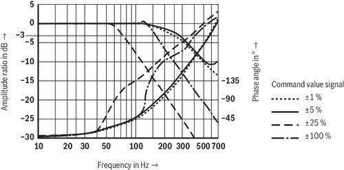
Frequency response with pp = 315 bar - measured with pressure rating 315 barbar
Dependency of the frequency f at -90° of the pilot pressure - measured with 315 bar pressure rating
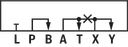
Symbols/Circuit diagrams
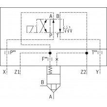
Type 4WSE3E...
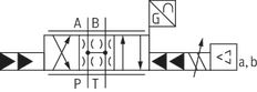
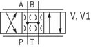
Symbol
With control spool symbol V, the following applies:
P → A: qVmax; B → T: qVmax
P → B: qVmax; A → T: qVmax
With control spool symbol V1-, the following applies:
P → A: qVmax; B → T: qV /2
P → B: qV /2; A → T: qVmax
Electrical connection
| Electrical interface Pin | A1 | C1 | F1 | |
| Current consumption at the mating connector port | A | < ±150 mA with ±15 V < 200 mA with 24 V | < 200 mA with 24 V | |
| B | ||||
| D | 0 ... ±0,05 mA | 0 ... ±10 mA | 4 ... 20 mA | |
| E | ||||
| Pin assignment | Contact | Supply voltage 15 | Supply voltage 24 | |||
| Interface | A1 | C1 | A1 | C1 | F1 | |
| Power supply | A | + 15 VDC | + 24 VDC | |||
| B | - 15 VDC | 0 VDC | ||||
| M0 | C | Reference to A, B 0 VDC | Not assigned | |||
| Differential command value input | D | 0 ... ± 10 V; Re > 100 kΩ | 0 ... ± 10 mA; Re = 100 Ω | 0 ... ± 10 V; Re > 100 kΩ | 0 ... ± 10 mA; Re = 100 Ω | 4 ... 20 mA; Re = 100 Ω |
| E | ||||||
| Actual value Reference with +24 V is pin B Reference with ±15 V is pin C | F | 0 ... ± 10 V; Ri ≈ 1 kΩ | 0 ... ±10 mA; Maximum load 1 kΩ | 0 ... ± 10 V; Ri ≈ 1 kΩ | 0 ... ±10 mA; Maximum load 1 kΩ | 4 ... 20 mA; load max. 500 Ω |
| Protective earthing conductor | PE | connected to valve housing | ||||
| One end of the shield must be connected to the control! | ||||||
Supply voltage:
±15 V ±3 %, residual ripple < 1 %
+24 VDC / 18 ... 35 V; full bridge rectification with smoothing capacitor 2200 μF = Imax = 230 mA
Command value: A1, C1:
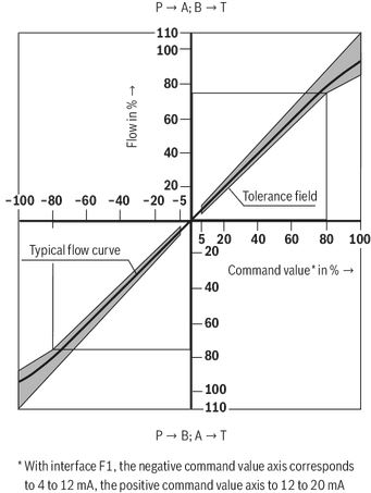
Reference potential at E and positive command value at D result in flow from P → A and B → T.
Reference potential at E and negative command value at D result in flow from P → B and A → T.
F1:
Reference potential at E and signal 12 to 20 mA at D result in flow from P → A and B → T.
Reference potential at E and signal 12 to 4 mA at D result in flow from P → B and A → T.
Actual value / measuring output:
The voltage / current signal is proportional to the control spool stroke and has the same sign as the command value.
Connection cable:
Recommendation:
- up to 25 m line length: Type LiYCY 7 x 0.75 mm2
- up to 50 m line length: Type LiYCY 7 x 1.0 mm2
Connect shield to ⊥ only on the supply side.
Notice:
Electrical signals provided via valve electronics (e.g. actual value) must not be used to switch off safety-relevant machine functions!
Block diagram / pin assignment
Dimensions
Dimensions in mm
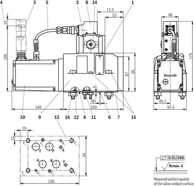
| 1 | Name plate complete valve |
| 2 | Name plate pilot control valve |
| 3 | Mating connector, separate order |
| 4 | Space required to remove the mating connector |
| 5 | PVC cable not resistant when in contact with HFD-R fluid |
| 6 | Locating pin (2x) G1 and G2 |
| 7 | Cover plate (for transport only) |
| 8 | Pilot control valve (2-stage) |
| 9 | Main stage (3rd stage) |
| 10 | Integrated electronics (OBE) |
| 11 | Identical seal rings for ports A, B, P, and T |
| 12 | Identical seal rings for ports X and Y The ports X and Y are also pressurized in the case of "internal" pilot oil supply |
| 13 | machined valve contact surface; porting pattern according to ISO 4401-07-07-0-05 |
| 14 | Exchangeable filter element with seals |
| 15 | Valve mounting screws (included in the scope of delivery): |
| 16 | Hexagon nuts (for transport only) |
Flushing plate with porting pattern according to ISO 4401-07-07-0-05
Dimensions in mm
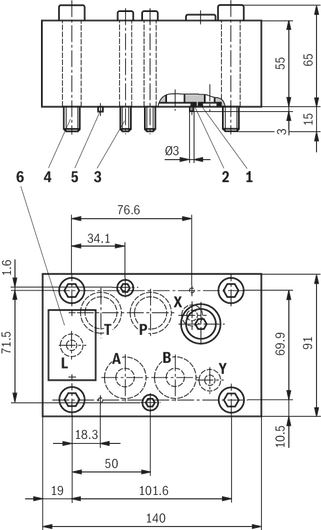
| 1 | R-ring 10 x 2 x 2 (ports L, X, Y) included in scope of delivery |
| 2 | R-ring 22.53 x 2.30 x 2.62 (ports P, T, A, B) included in scope of delivery |
| 3 | Mounting screws (included in the scope of delivery):2 hexagon socket head cap screws ISO 4762 - M6 x 70- 10.9-flZn-240h-L, MA = 15.5 Nm ± 20 % |
| 4 | Mounting screws (included in the scope of delivery):4 hexagon socket head cap screws ISO 4762 - M10 x 70- 10.9-flZn-240h-L, MA = 75 Nm ± 20 % |
| 5 | 2 locating pins 3 x 8 - A2C DIN EN 28741 |
| 6 | Name plate |
To ensure proper operation of the servo valves, it is necessary to flush the system before commissioning.
The following values are guidelines for the flushing time per system: t ≥ V : QV x 5
t = flushing time in h
V = tank capacity in l
QV = Pump flow in l/min
When replenishing more than 10% of the tank capacity, the flushing procedure must be repeated.
The use of a directional valve with port according to ISO 4401-07-07-0-05 is suited better than a flushing plate. With this valve, you can also flush the actuator ports.
Symbol
| 1) | with FKM seals |
| 2) | Material no. R900959376 (without fig.) |
| 3) | Weight: 4.5 kg |
Accessories
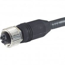
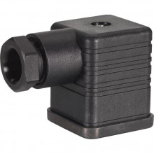
Mating connectors for valves with round connector, 6-pole + PE
7P Z31
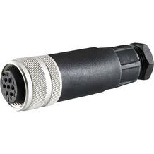
Mating connectors for valves with round connector, 6-pole + PE
7P Z31
- For valves with round connector according to EN 175201-804, 6-pole + PE as well as 6-pole, compatible with VG 95328
Downloads
 | Declaration on environmental compatibility in the field of EMC, climate and mechanical stress Data Sheet | RE29620-U | 2009-04-06 | English | PDF | 140k Product Groups: Directional servo-valves 4WSE3E 16 (25, 32) |
| Directional servo-valve of 4-way design Data Sheet | RE29620 | 2012-03-31 | English | PDF | 1.2MB Product Groups: Directional servo-valves Type 4WSE3E 16 |
| Declaration on environmental compatibility in the field of EMC, climate and mechanical stress Data Sheet | RE29620-U | 2009-04-06 | English | PDF | 140k Product Groups: Directional servo-valves 4WSE3E 16 (25, 32) |


Цена по запросу
Нет отзывов об этом товаре.