

Артикул: RX7684
Proportional pressure reducing valve, pilot-operated ZDRE 10, ZDREE 10
Доступно к заказу
Цена по запросу
И выбери подходящего.
Description
- Size 10
- Component series 2X
- Max. operating pressure 315 bar
- Flow, max. 80 l/min
Features
- Pilot-operated proportional valve for system pressure reduction
- Operation by rotatable proportional solenoid
- Sandwich plate design
- Porting pattern according to DIN 24340 form A and ISO 4401
- 4 pressure ratings
- Valve and control electronics from a single source
- External control electronics for type ZDRE
- Linear pressure/command value characteristic curve
- Integrated electronics (OBE) with little manufacturing tolerance of the command value pressure characteristic curve with type ZDREE
Product description
Valves of type ZDRE... are pilot-operated pressure reducing valve in sandwich plate design and 3-way version, i. e. with pressure limitation of the actuator pressure. They are used for reducing a system pressure.
They mainly consist of pilot control component (1) with proportional solenoid (2), main valve (3) and control spool (4). The pressure in channel P1 is set in a command value-dependent form via the proportional solenoid (2). In rest position, i. e. without pressure in channel P2, the control spool (4) opens the connection from channel P2 to P1. The pressure in channel P1 acts on the spool face (6) via the bore (5). The pilot oil for the pilot valve is taken from channel P1 and flows via the bore (5) and the nozzle (7) into the spring chamber (8). From there, it flows back to the tank via the valve seat (9), the bore (10) and the Y line. The pressure required in channel P1 is preset at the related amplifier. The proportional solenoid moves the valve poppet (11) in the direction of the valve seat (9) and increases the pressure in the spring chamber (8). In this way, the two chambers (6) and (8) are pressure-compensated and the compression spring (12) moves the piston (4) to the right in opening direction P2 to P1. As soon as the actuator pressure P1 has increased to the value set at the pilot valve, the valve poppet (11) opens and limits the pressure in the spring chamber (8). The control spool (4) now moves to the left in control position. If the actuator pressure P1 exceeds the value set at the pilot valve, the control spool is moved further to the left. It blocks the flow from P2 to P1 and opens the connection from P1 to tank TA1 at the control edge (13) until the pressure has dropped again to the set value.
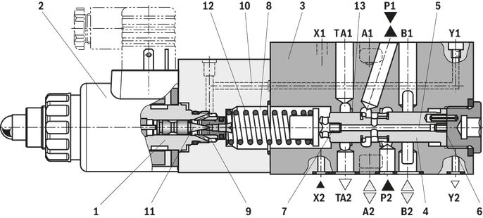
Valves of type ZDREE... are pilot-operated pressure reducing valves in sandwich plate design and 3-way version, i. e. with pressure limitation of the actuator pressure. They are used for reducing a system pressure.
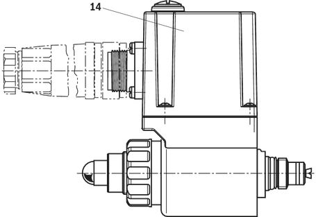
They mainly consist of pilot control component (1) with proportional solenoid (2), main valve (3) and control spool (4). The control electronics (OBE) in the housing (14) maintain the supply and command value voltage via the mating connector. At the factory, the command value pressure characteristic curve is adjusted with little manufacturing tolerance. The pressure in channel P1 is set in a command value-dependent form via the proportional solenoid (2). In rest position, i. e. without pressure in channel P2, the control spool (4) opens the connection from channel P2 to P1. The pressure in channel P1 acts on the spool face (6) via the bore (5). The pilot oil for the pilot valve is taken from channel P1 and flows via the bore (5) and the nozzle (7) into the spring chamber (8). From there, it flows back to the tank via the valve seat (9), the bore (10) and the Y line. The pressure required in channel P1 is preset at the related
amplifier. The proportional solenoid moves the valve poppet (11) in the direction of the valve seat (9) and increases the pressure in the spring chamber (8). In this way, the two chambers (6) and (8) are pressure-compensated and the compression spring (12) moves the piston (4) to the right in opening direction P2 to P1. As soon as the actuator pressure P1 has increased to the value set at the pilot valve, the valve poppet (11) opens and limits the pressure in the spring chamber (8). The control spool (4) now moves to the left in control position. If the actuator pressure P1 exceeds the value set at the pilot valve, the control spool is moved further to the left. It blocks the flow from P2 to P1 and opens the connection from P1 to tank TA1 at the control edge (13) until the pressure has dropped again to the set value.
Pilot oil supply for the upstream directional valve
| Notice:- With the direct operated directional valve, there is no sealing for ports X and Y at the connection surface of the housing. To ensure that no hydraulic fluid leaks, the pilot oil supply from P2 to X and the pilot oil return between directional valve and ZDRE(E) has to be closed (version XL).- Leakage caused by the control spool play from P to B can lead to a pressure build-up in port B!- A pilot-operated proportional directional valve in connection with ZDRE(E) has to have an external pilot oil supply. | |
| With versions XY and XL, the connection between P2 and X is closed | With versions Y and L, port X in the subplate must be closed. |
Type ZDRE(E) 10...2X/...XY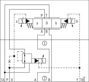 | Type ZDRE(E) 10...2X/...Y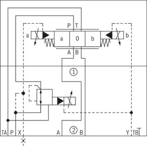 |
Type ZDRE(E) 10...2X/...XL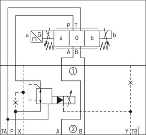 | Type ZDRE(E) 10...2X/...L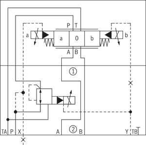 |
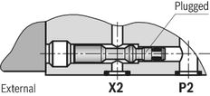 | 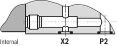 |
Type code
| 01 | 02 | 03 | 04 | 05 | 06 | 07 | 08 | 09 | 10 | 11 | 12 | 13 | 14 | 15 | ||
| Z | DRE | 10 | VP | 2 | - | 2X | / | M | G24 | * |
| 01 | Sandwich plate | Z | |
| 02 | Proportional pressure reducing valve | DRE | |
| 03 | For external analog electronics | no code | |
| With integrated control electronics | E | ||
| Size | |||
| 04 | Size 10 | 10 | |
| 05 | Pressure reduction in channel P | VP | |
| 06 | Preferred position of mating connector | 2 | |
 The mating connector can be brought to the desired position when the nut was loosened | |||
| 07 | Component series 20 ... 29 (20 ... 29: unchanged installation and connection dimensions) - Size 6 | 2X | |
| Pressure rating | |||
| 08 | Up to 50 bar | 50 | |
| Up to 100 bar | 100 | ||
| Up to 200 bar | 200 | ||
| Up to 315 bar | 315 | ||
| Pilot oil supply and return | |||
| 09 | Pilot oil supply for the directional valve from port P2, external pilot oil return for the directional valve and ZDRE | Y | |
| External pilot oil supply for the directional valve, external pilot oil return for the directional valve and ZDRE | XY | ||
| Pilot oil supply for the directional valve from port P2, internal pilot oil return for the directional valve and external pilot oil return for ZDRE | L | ||
| Pilot oil supply from P2 to X is closed (direct actuated directional valve does not require pilot oil), pilot oil return of directional valve is closed (direct actuated directional valve does not require pilot oil return), external pilot oil return for ZDRE | XL | ||
| 10 | Without check valve | M | |
| Supply voltage of the control electronics | |||
| 11 | Direct voltage 24 V | G24 | |
| Electrical connection | |||
| 12 | For type ZDRE: | Without mating connector; connector DIN EN 175301-803 | K4 |
| For type ZDREE: | Without mating connector; connector DIN EN 175201-804 | K31 | |
| Electrical interface | |||
| 13 | For type ZDRE: | no code | |
| Command value 0 … 10 V | A1 | ||
| Command value 4 to 20 mA | F1 | ||
| Seal material | |||
| 14 | NBR seals | M | |
| FKM seals | V | ||
| 15 | Further details in the plain text | * | |
Technical data
general
| Type | ZDRE | ZDREE | |
| Size | 10 | ||
| Component series | 2X | ||
| Installation position | Preferred position of the proportional solenoid downward or horizontal | ||
| Weight | kg | 5.1 | 5.2 |
| Storage temperature range | °C | -20 … +80 | |
| Ambient temperature range | °C | -20 … +70 | -20 … +50 |
hydraulic
| Type | ZDRE | ZDREE | ||
| Size | 10 | |||
| Maximum operating pressure | bar | 315 | ||
| Maximum operating pressure | Port P1 | bar | 315 | |
| Port P2 | bar | 350 | ||
| Anschluss A | bar | 350 | ||
| Port B | bar | 350 | ||
| Port T | bar | 250 | ||
| Port X | bar | 350 | ||
| Port L | separate and depressurized to the tank | |||
| Maximum set pressure in port P1 | Pressure rating 50 bar | bar | 50 | |
| Pressure rating 100 bar | bar | 100 | ||
| Pressure rating 200 bar | bar | 200 | ||
| Pressure rating 315 bar | bar | 315 | ||
| Minimum set pressure 1) | See characteristic curves | |||
| Pilot oil volume range | cm³ | 0,6 … 0,9 | ||
| Maximum flow | l/min | 80 | ||
| Hydraulic fluid | see table | |||
| Hydraulic fluid temperature range | °C | -20 … +80 | ||
| Viscosity range | mm²/s | 15 … 380 | ||
| Maximum admissible degree of contamination of the hydraulic fluid, cleanliness class according to ISO 4406 (c) 2) | Class 20/18/15 according to ISO 4406 (c) | |||
| Hysteresis 3) | % | ± 3 | ||
| Repetition accuracy 3) | % | < ± 2 | ||
| Linearity 3) | % | ± 3.5 | ||
| Manufacturing tolerance of the command value pressure characteristic curve 4) | % | ± 5 | ± 1.5 | |
| Step response 5) | 10 ... 90% | ms | ≈ 160 | |
| 90 ... 10% | ms | ≈ 160 | ||
| 1) | in port P1 with command value 0 |
| 2) | The cleanliness classes specified for the components must be adhered to in hydraulic systems. Effective filtration prevents faults and simultaneously increases the life cycle of the components. For the selection of the filters, see www.boschrexroth.com/filter. |
| 3) | Of the maximum set pressure |
| 4) | of the maximum set pressure, related to the hysteresis characteristic curve, pressure increasing |
| 5) | measured with standing hydraulic fluid column, 5 liter at port P1 |
| Hydraulic fluid | Classification | Suitable sealing materials | Standards |
| Mineral oils and related hydrocarbons | HL, HLP | NBR / FKM | DIN 51524 |
| Important information on hydraulic fluids: For more information and data on the use of other hydraulic fluids please contact us. The flash point of the process and operating medium used must be 40 K over the maximum solenoid surface temperature. | |||
electrical
| Type | ZDRE | ZDREE | ||
| Power supply | Nominal voltage | VDC | 24 | |
| Lower limit value | VDC | 21 | ||
| Upper limit value | VDC | 35 | ||
| Minimum solenoid current | mA | 100 | ||
| Maximum solenoid current | mA | 1760 | ||
| Solenoid coil resistance | Cold value at 20 °C | Ω | 5.5 | |
| Solenoid coil resistance | Maximum hot value | Ω | 8.05 | |
| Duty cycle | % | 100 | ||
| Current consumption | A | ≤ 1.5 | ||
| Required fuse protection | 2, time-lag | |||
| Inputs | Voltage | V | 0 … 10 | |
| Current | mA | 4 … 20 | ||
| Outlet | Actual current value | 1 mV ≙ 1 mA | ||
| Protection class according to DIN EN 60529 | IP65 (If a suitable and a correctly mounted mating connector are used.) | |||
Diagrams/characteristic curves
(measured with HLP46, ϑOil = 40 ±5 °C)
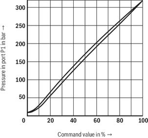
Reduced pressure at port P1 dependent on the command value (manufacturing tolerance)
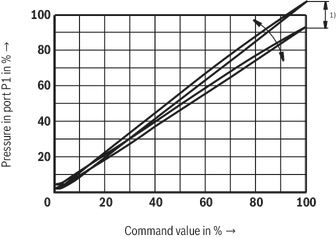
Pressure at port P1 dependent on the command value (with flow 0 l/min)
Pressure rating 50 bar
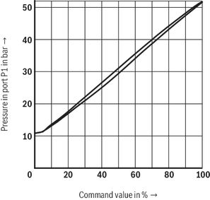
Pressure rating 100 bar
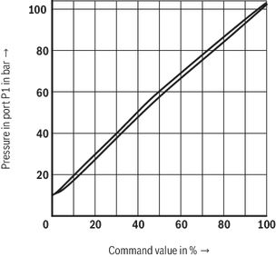
Pressure rating 200 bar
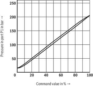
Pressure rating 315 bar
Pressure differential dependent on the flow

Pressure differential dependent on the flow

Pressure at port P1 dependent on the flow
Pressure rating 50 bar

Pressure rating 100 bar

Pressure rating 200 bar

Pressure rating 315 bar

Minimum set pressure dependent on the flow at command value 0

Symbols/Circuit diagrams
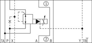
Type ZDRE10VP...L
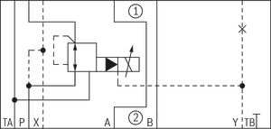
Type ZDRE10VP...XL
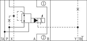
Type ZDRE10VP...Y
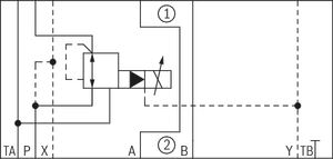
Type ZDRE10VP...XY
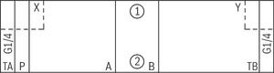
Type sandwich plate HSZ 10 B097-3X/M01
Type ZDREE10VP...XL
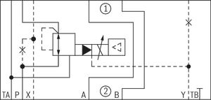
Type ZDREE10VP...L
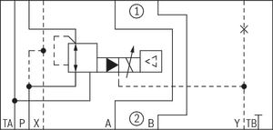
Type ZDREE10VP...Y
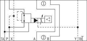
Type ZDREE10VP...XY
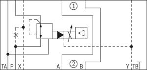
Electrical connection
load errorDimensions
load errorDownloads
 | Proportional pressure reducing valve, pilot operated Data Sheet | RE29279 | 2010-12-22 | English | PDF | 567k Product Groups: Pilot operated Types ZDRE, ZDREE |

Нет отзывов об этом товаре.