
Доступно к заказу
Цена по запросу
И выбери подходящего.
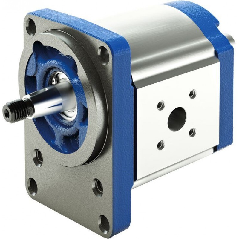
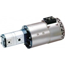
Внешний шестеренчатый насос высокой производительности AZPF — это гидравлический насос.
Основные функции и задачи, выполняемые данным насосом:
- Обеспечение непрерывной перекачки жидкости из одного места в другое. Он может работать с различными типами жидкостей, включая масла, гидравлические жидкости и воду.
- Создает высокое давление в системе, что позволяет передвигать жидкость через трубопроводы и обеспечивать необходимую силу для работы гидравлических актуаторов.
- Регулирование потоком жидкости в системе. Это особенно полезно в приложениях, где требуется изменение скорости или направления движения гидравлических актуаторов.
- Управление различными гидравлическими системами, включая системы подъема и перемещения, системы управления нагрузкой и системы управления направлением движения.
Насосы AZPF применяются в промышленных системах, например в гидравлических прессах, станках с ЧПУ, промышленных роботах и автоматизированных производственных линий. А также в системах энергетической отрасли, включая гидроэлектростанции, ветряные электростанции и солнечные электростанции.
Основные характеристики внешнего шестеренчатого насоса AZPF:
- высокая производительность;
- высокое давление;
- компактный дизайн;
- высокая надежность;
- регулирование.
Description
- Platform F
- Fixed displacement
- Size 4 … 28
- Continuous pressure up to 250 bar
- Intermittent pressure up to 280 bar
Features
- Consistent high quality based on large-volume production
- Long service life
- Slide bearings for high loads
- Drive shafts according to ISO or SAE and customer-specific solutions
- Line ports: connection flange or screw thread
- Combination of several pumps possible
Product description
General information
It is the central task of external gear pumps to convert mechanical energy (torque and speed) into hydraulic energy (flow and pressure). To reduce heat losses, Rexroth’s external gear units offer very high efficiencies. They are realized by pressure-dependent gap sealing and highly precise production technology.
Rexroth external gear pumps are built in four frame sizes: Platform B, F, N and G. Within each platform different sizes can be realized by different gear widths. The pumps are available in the versions Standard, High-Performance, SILENCE und SILENCE PLUS. Further configuration variants are given by different flanges, shafts, valve arrangements and multiple pump combinations.
Pumping principle
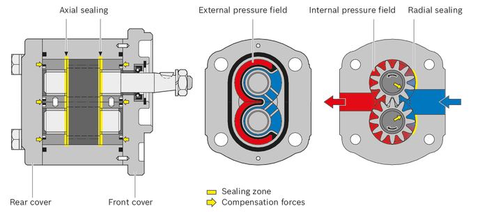
Due to the teeth moving apart during the rotation from the tooth mesh, the gear chambers become clear. The resulting negative pressure as well as the atmospheric pressure on the hydraulic fluid level in the reservoir cause hydraulic fluid to flow from the reservoir to the pump. This hydraulic fluid fills the gear chambers and is transported in them in the direction of the arrow (see sectional drawing) along the housing from the suction side to the pressure side. The teeth mesh again then, force the hydraulic fluid out of the gear chambers and prevent it from flowing back to the suction chamber.
Construction
The external gear pump consists essentially of a pair of gear wheels supported in bearing bushings and the housing with a front cover and an end cover.
The drive shaft protrudes from the front cover where it is usually sealed by the shaft seal. The bearing forces are absorbed by slide bearings. These bearings were designed for high pressures and have excellent emergency running properties, especially at low rotational speeds.
The gear wheels have 12 teeth. This keeps both flow pulsation and noise emission to a minimum. The sealing of the pressure chambers is achieved by forces depending on the working pressure. This ensures optimum efficiency. The working pressure generated in the gear chambers is transferred to the outside of the bearing bushings in specifically designed pressure fields in such a way that they are pressed against the gears and seal them up. The pressurized compression areas are limited by special seals. The seal in the area between the gear teeth and the housing is ensured by the smallest of gaps that are set depending on the pressure between the gear teeth and housing.
External gear pump layout
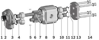
|
1 |
Retaining ring |
8 |
Housing seal ring |
|
2 |
Shaft seal |
9 |
Pump housing |
|
3 |
Front cover |
10 |
Bearing bushing |
|
4 |
Slide bearings |
11 |
Axial field seal |
|
5 |
Centering pin |
12 |
Supporting element |
|
6 |
Gear wheel |
13 |
Rear cover |
|
7 |
Drive shaft |
14 |
Torx screws |
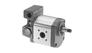
Gear pumps with integrated valves
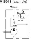
In order to reduce piping complexity, a flow control valve or pressure-relief valve can be integrated in the cover of the gear pump. Such solutions are used, for instance, for the hydraulic oil supply of power steering systems. The pump delivers a constant flow or maximum
pressure irrespective of the rotational speed. The residual flow distributed externally to other consumers.
Pressure relief valve, external pressure discharge
p1 = 5 to 250 bar
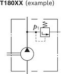
Pressure relief valve, pressure discharge into suction line
p1 = 5 to 250 bar
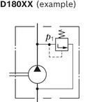
3-way flow control valve, residual flow distributed externally, loadable
qconst = 2 to 30 l/min
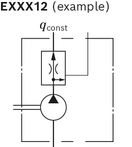
3-way flow control valve, residual flow returned in suction line
qconst = 2 to 30 l/min
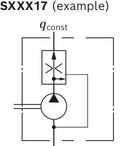
3-way flow control valve with pressure relief valve, residual flow returned in suction line
qconst = 2 to 30 l/min; p1 = 100 to 180 bar
Type code
Type code single pump

| 1) | Corrosion-protected version, details see "Technical data“ |

| 1) | For further information on special versions, please contact us. |
Note
- Not all of the variants according to the type code are possible.
- Please select the desired pump with the help of the selection table (preferred types ) or after consultation with Bosch Rexroth.
- Special options are available on request.
Type code multiple pump

| 1) | A letter is to be selected for each pump stage, e.g. 3-way pump AZPJ + AZPJ + AZPB: JJB |
| 2) | A numerical value is to be selected for each pump stage, e.g.3-way pump 028/016/2.0 |
| 3) | A numerical value is to be selected for each pump stage, e.g.3-way pump 202020 |
Note
- Not all of the variants according to the type code are possible.
- Please select the desired pump with the help of the selection table (preferred types ) or after consultation with Bosch Rexroth.
- Special options are available on request.
Example 4-way pump:
AZPG…032… + AZPG…022… + AZPJ…016… + AZPJ…012…

Technical data
Table of values
|
Size |
4 | 5 | 8 | 11 | 14 | 16 | 19 | 22 | 4 | 5 | 8 | 11 | 14 | 16 | 19 | 22 | 25 | 28 | ||||
|
Series |
Series 1x | Series 2x | ||||||||||||||||||||
|
Displacement |
Vg |
cm³ |
4 | 5.5 | 8 | 11 | 14 | 16 | 19 | 22.5 | 4 | 5.5 | 8 | 11 | 14 | 16 | 19 | 22.5 | 25 | 28 | ||
|
Pressure at suction port S 1) |
absolute |
pe |
bar |
0.7 ... 3 | ||||||||||||||||||
|
Maximum continuous pressure |
p1 |
bar |
250 | 250 | 250 | 250 | 250 | 250 | 210 | 180 | 250 | 250 | 250 | 250 | 250 | 250 | 250 | 220 | 195 | 170 | ||
|
Maximum intermittent pressure 2) |
p2 |
bar |
280 | 280 | 280 | 280 | 280 | 280 | 230 | 210 | 280 | 280 | 280 | 280 | 280 | 280 | 280 | 250 | 225 | 200 | ||
|
Maximum pressure peaks |
p3 |
bar |
300 | 300 | 300 | 300 | 300 | 300 | 250 | 230 | 300 | 300 | 300 | 300 | 300 | 300 | 300 | 290 | 265 | 240 | ||
|
Minimum speed at |
ν = 12 mm²/s |
p < 100 bar |
nmin |
rpm |
600 | 500 | 500 | 500 | 500 | 500 | 500 | 500 | 600 | 500 | 500 | 500 | 500 | 500 | 500 | 500 | 500 | 500 |
|
p = 100 bar … 180 bar |
nmin |
rpm |
1200 | 1200 | 1000 | 1000 | 800 | 800 | 800 | 800 | 1200 | 1200 | 1000 | 1000 | 800 | 800 | 800 | 800 | 800 | 800 | ||
|
p = 180 bar … p2 |
nmin |
rpm |
1400 | 1400 | 1400 | 1200 | 1000 | 1000 | 1000 | 1000 | 1400 | 1400 | 1400 | 1200 | 1000 | 1000 | 1000 | 1000 | 1000 | 1000 | ||
|
ν = 25 mm²/s |
at p2 |
nmin |
rpm |
700 | 700 | 700 | 600 | 500 | 500 | 500 | 500 | 700 | 700 | 700 | 600 | 500 | 500 | 500 | 500 | 500 | 500 | |
|
Maximum speed |
at p2 |
nmax |
rpm |
4000 | 4000 | 4000 | 3500 | 3000 | 3000 | 3000 | 2500 | 4000 | 4000 | 4000 | 3500 | 3000 | 3000 | 3500 | 3500 | 3000 | 3000 | |
| 1) | In the case of tandem pumps, the suction-side pressure difference between the individual pump stages must not exceed 0.5 bar. |
| 2) | Limited service life with threaded line ports and p2 > 210 bar |
General technical data
|
Weight |
m |
kg |
See chapter Dimensions |
|
Installation position |
No restrictions |
||
|
Mounting type |
Flange or through-bolting with spigot |
||
|
Line connections |
See chapter Dimensions |
||
|
Direction of rotation, viewed on drive shaft |
Clockwise or counter-clockwise, the pump may only be driven in the direction indicated |
||
|
Drive shaft loading |
Axial and radial forces only after consultation |
||
|
Ambient temperature range |
t |
°C |
-30 to +80 with NBR seals (NBR = nitrile rubber) |
|
-20 to +110 with FKM seals (FKM = fluoroelastomer) |
|||
Corrosion protection
|
Version 1 (phosphated): |
The surface serves for protection against flash rust during transport or as priming for painting. |
|
|
Version 2 (galvanized, passivated): |
Degree of corrosion and rust according to DIN EN ISO 9227 |
Test duration 96 h: no red rust |
Note
- Safety requirements pertaining to the whole systems are to be observed.
- Please contact us for applications with frequent load changes.
Pressure definition
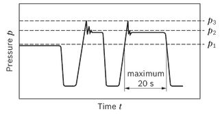
| p1: Continuous pressure max. | |
| p2: Intermittent pressure max. | |
| p3: Pressure peaks max. |
|
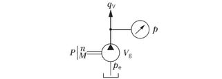
Determining the operating characteristics |
||
|
Flow |
 |
[l/min] |
|
Torque |
 |
[Nm] |
|
Power |
 |
[kW] |
|
Key |
|
|
Vg |
Displacement per revolution [cm3] |
|
Δp |
Differential pressure [bar] |
|
n |
Rotational speed [rpm] |
|
ηv |
Volumetric efficiency |
|
ηhm |
Hydraulic-mechanical efficiency |
|
ηt |
Total efficiency (ηt = ηv • ηhm) |
Note
You can find diagrams for a rough calculation in chapter "Diagrams / Characteristic curves".
Hydraulic fluids
The external gear unit is designed for operation with HLP mineral oil according to DIN 51524, 1-3. Under higher load, however, Bosch Rexroth recommends at least HLP compliant with DIN 51524 Part 2.
See the following data sheet for application instructions and requirements for selecting hydraulic fluid, behavior during operation as well as disposal and environmental protection before you begin project planning:
- 90220: Hydraulic fluids based on mineral oils and related hydrocarbons
Other hydraulic fluids on request.
Selection of hydraulic fluid
Bosch Rexroth evaluates hydraulic fluids on the basis of the Fluid Rating according to the technical data sheet 90235.
Hydraulic fluids with positive evaluation in the Fluid Rating are provided in the following technical data sheet:
- 90245: Bosch Rexroth Fluid Rating List for Rexroth hydraulic components (pumps and motors)
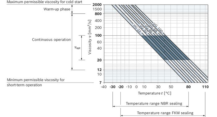
The hydraulic fluid should be selected so that the operating viscosity in the operating temperature range is within the optimum range (νopt; see selection diagram).
Viscosity and temperature of hydraulic fluids
|
Viscosity range |
|
|
Permissible in continuous operation |
ν = 12 … 800 mm²/s |
|
Recommended in continuous operation |
νopt = 20 … 100 mm²/s |
|
Permissible for cold start |
νmax ≤ 2000 mm²/s |
|
Temperature range |
|
|
With NBR seals (NBR = nitrile rubber) |
t = -30 °C … +80 °C |
|
With FKM seals (FKM = fluoroelastomer) |
t = -20 °C … +110 °C |
Observe the instructions for the filtration of the hydraulic fluid (see chapter Project planning information).
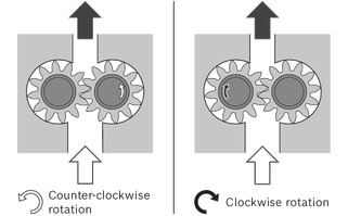
Direction of rotation
The dimensional drawings in the chapter Dimensions represent pumps for clockwise rotation. The position of the drive shaft or the position of suction and pressure port changes for counter-clockwise rotation.
Direction of rotation, viewed on drive shaft
Drives
1. Elastic couplings
- The coupling must not transfer any radial and axial forces onto the pump.
- The maximum admissible radial run-out deviation from the shaft to the fitting slot is 0.2 mm.
- Admissible shaft shifting see installation information of the coupling manufacturers.
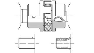
2. Coupling sleeve
- To be used on splined shaft profile according to DIN and SAE.
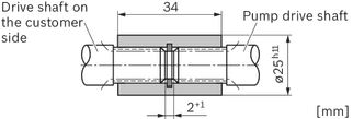
- Attention: No radial or axial forces are permitted on the pump shaft or coupling sleeve. The coupling sleeve must be free to move axially.
- The distance between the pump drive shaft and drive shaft on the customer side must 2+1 mm.
- Provide installation space for the snap ring.
- Oil-bath or oil-mist lubrication is required.
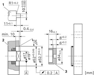
3. Tang drive coupling
- For attaching the pump directly to an electric motor or combustion engine, gear, etc.
- The pump shaft has a special tang drive and driver (3) (scope of delivery see offer drawing)
- There is no shaft sealing
- Drive-side installation and sealing according to the following recommendations and dimensions
- Drive shaft on the customer side (1)
- Case-hardening steel DIN EN 10084 e.g. 20MnCrS5 case-hardened 0.6 mm deep; HRC 60±3
- Seal ring running surface ground without rifling Rt ≤ 4 μm
- Radial shaft seals on the customer side (2)
- Provide with rubber cover (see DIN 3760, type AS or double-lipped ring)
- Provide installation edge with 15° slant or install shaft seal with protection sleeve
AZPF-1x

AZPF-2x
| 1) | See offer drawing |
4. V-belts and straight gear wheels or helical toothed gear drives without outrigger bearing
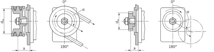
For V-belt or gear wheel drives, please contact us specifying the application and mounting conditions (dimensions a, dm, dw and angle α). For helical toothed gear drives, details of the helix angle β are also required.
5. Outrigger bearing
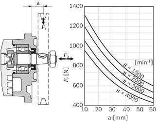
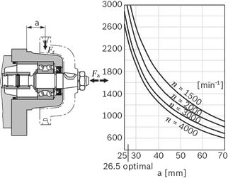
Outrigger bearing are offered to eliminate possible problems when the pumps are driven by V-belts or gear wheels. The diagrams show the radial and axial load capacity in relation to a bearing service life of LH = 1000 h.
Front cover A (type 1)
Front cover G (type 2)
Maximum transferable drive torques
Splined shafts
|
Drive shaft |
Mmax |
Size |
p2 max |
p2 max |
|
|
Code |
Designation |
Nm |
bar |
bar |
|
| F | DIN 5482 B17 × 14 | 100 | 4 … 16 | 280 | 280 |
| 19 | 230 | ||||
| 22 | 210 | 250 | |||
| 25 | - | 225 | |||
| 28 | - | 200 | |||
| R | SAE J744 16-4 9T | 110 | 4 … 16 | 280 | 280 |
| 19 | 230 | ||||
| 22 | 210 | 250 | |||
| 25 | - | 225 | |||
| 28 | - | 200 | |||
| P | SAE J744 19-4 11T | 180 | 4 … 16 | 280 | 280 |
| 19 | 230 | ||||
| 22 | 210 | 250 | |||
| 25 | - | 225 | |||
| 28 | - | 200 | |||
Tapered shafts
|
Drive shaft |
Mmax |
Size |
p2 max |
p2 max |
|
|
Code |
Type |
Nm |
bar |
bar |
|
| C | 1 : 5 | 155 | 4 … 16 | 280 | 280 |
| 19 | 230 | ||||
| 22 | 210 | 250 | |||
| 25 | - | 225 | |||
| 28 | - | 200 | |||
| H | 1 : 8 | 160 | 4 … 16 | 280 | 280 |
| 19 | 230 | ||||
| 22 | 210 | 250 | |||
| 25 | - | 225 | |||
| 28 | - | 200 | |||
Parallel keyed shafts
|
Drive shaft |
Mmax |
Size |
p2 max |
|
|
Code |
Designation |
Nm |
bar |
|
| Q | SAE J744 16-1 A | 55 | 4 … 11 | 280 |
| 14 | 220 | |||
| 16 | 190 | |||
| 19 | 160 | |||
| 22 | 130 | |||
| 25 | 120 | |||
| 28 | 110 | |||
| A | ISO ⌀18 mm | 75 | 4 … 14 | 280 |
| 16 | 260 | |||
| 19 | 220 | |||
| 22 | 180 | |||
| 25 | 160 | |||
| 28 | 150 | |||
Tang drive
|
Drive shaft |
Mmax |
Size |
p2 max |
p2 max |
|
|
Code |
Designation |
Nm |
bar |
bar |
|
| N | Tang drive | 65 | 4 … 11 | 280 | |
| 14 | 260 | ||||
| 16 | 220 | ||||
| 19 | 190 | ||||
| 22 | 160 | ||||
| 85 | 4 … 16 | 280 | |||
| 19 | 250 | ||||
| 22 | 210 | ||||
| 25 | 190 | ||||
| 28 | 170 | ||||
With outrigger bearing
|
Drive shaft |
Outrigger bearing |
Mmax |
Size |
p2 max |
p2 max |
|
Code |
Type (code) |
Nm |
bar |
bar |
|
| S | Type 1 (A) (with tang drive coupling) | 65 | 4 … 11 | 280 | 280 |
| 14 | 260 | ||||
| 16 | 230 | 250 | |||
| 19 | 190 | 190 | |||
| 22 | 160 | 160 | |||
| 25 | 140 | 140 | |||
| 28 | 130 | 130 | |||
| Type 1 (A) (with sleeve) | 160 | 4 … 16 | 280 | 280 | |
| 19 | 230 | ||||
| 22 | 210 | 250 | |||
| 25 | - | 225 | |||
| 28 | - | 200 | |||
| Type 2 (G) | 4 … 16 | 280 | 280 | ||
| 19 | 230 | ||||
| 22 | 210 | 250 | |||
| 25 | - | 225 | |||
| 28 | - | 200 |
Multiple gear pumps
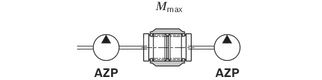
Gear pumps are well-suited to multiple arrangements, whereby the drive shaft of the first pump stage is extended to a second and possibly third pump stage. The shaft of the individual pump sections are normally connected via a driver or via a splined coupling (reinforced
through drive).
The individual pump stages are usually hydraulically isolated and have separate suction ports. On request a common suction port or separated but hydraulically connected suction ports are available.
For the configuration of multiple pumps, Bosch Rexroth recommends arranging the pump stage with the largest displacement on the drive side.
Note
Basically, the parameters of the single pumps apply, however certain restrictions need to be observed:
- Maximum rotational speed: This is determined by the largest pump stage used.
- Pressures: These are restricted by the maximum transmissible torques of the drive shaft, the through drive and the driver.
Addition of drive torques
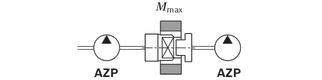
Please note, that in multiple pump arrangements the drive torques of the single pumps stages will add up according to the following formula:

| 1) | Mmax: see table above "Maximum transferable drive torques" |
This may result in pressure restrictions for the respective pump stages.
Standard through drive (tang drive coupling)
In the case of AZPF pumps the driver for the following pump stage can carry a load of up to Mmax = 65 Nm (AZPF-1x) resp. Mmax = 85 Nm (AZPF-2x).
Please note possibly resulting pressure restrictions for the following pump stages. Subsequent pumps of a smaller series determine the max. transmissible torque.
|
Following pump |
Mmax [Nm] |
|
|
Platform F |
AZPF-1x |
65 |
|
AZPF-2x |
85 |
|
|
AZPS-1x |
65 |
|
|
AZPS-2x |
85 |
|
|
AZPJ |
65 |
|
|
Platform B |
AZPB-3x |
25 |
Reinforced through drives
For applications with higher transfer torques or torsional vibrations reinforced through drives up to Mmax = 160 Nm are available. Lay out design on request.
Diagrams/characteristic curves
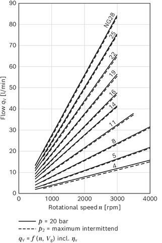
Flow characteristic curves
Note
- Characteristic curves measured at ν = 32 mm²/s and t = 50 °C.
Power diagrams
Size 4

Size 5
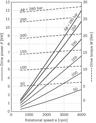
Size 8
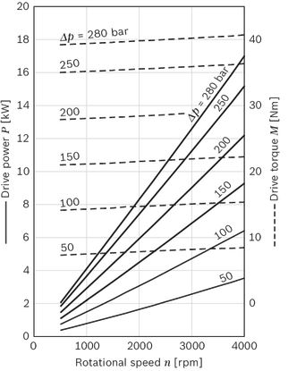
Size 11
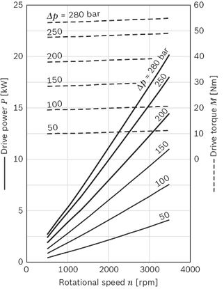
Size 14
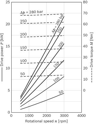
Size 16
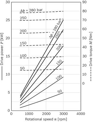
Size 19
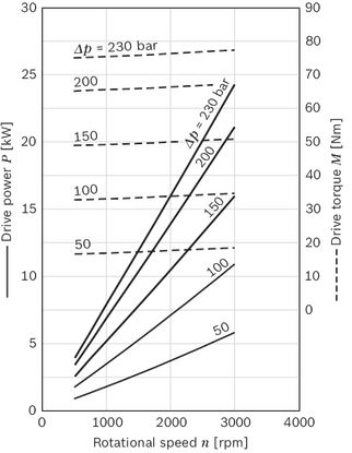
Size 22
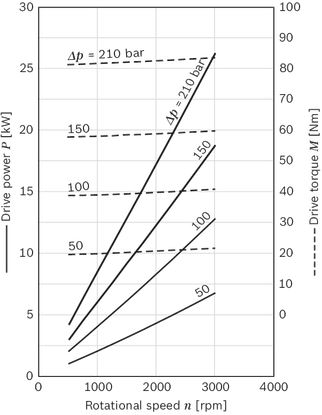
Size 25
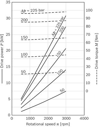
Size 28
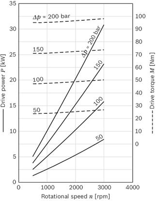
Noise charts
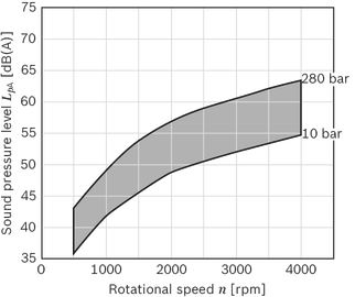
Noise levels dependent on the rotational speed, pressure range between 10 bar and pressure value p2 (see chapter "Technical data").
These are typical characteristic values for the respective size. They describe the airborne sound emitted solely by the pump.
Ambient influences (installation site, piping, other system components) were not taken into account.
The values refer to one individual pump.
Note
- Characteristic curves measured at ν = 32 mm²/s and t = 50 °C.
- Sound pressure level calculated from noise measurements made in the low reflection measuring room according to DIN 45635, Part 26.
- Distance from measuring sensor to pump: 1 m.
Size 4
Size 5
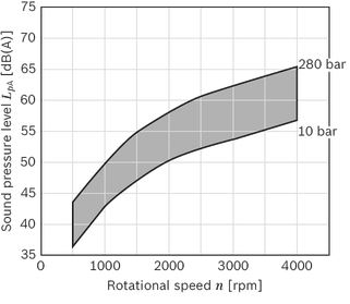
Size 8
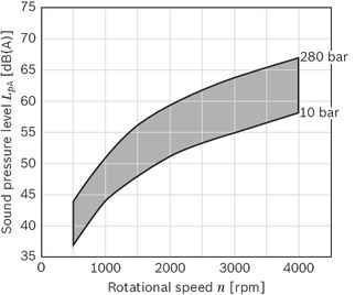
Size 11
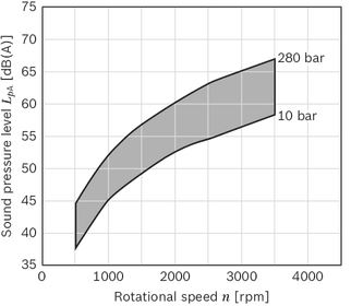
Size 14
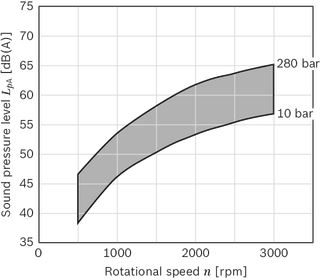
Size 16
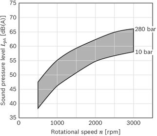
Size 19
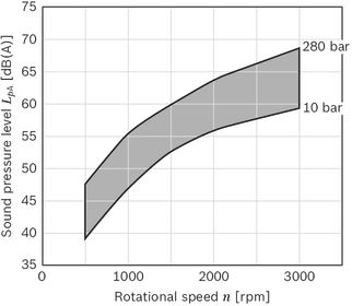
Size 22

Size 25

Size 28
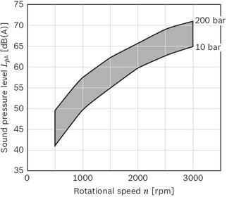
Dimensions
Project planning information
Technical data
All mentioned technical data are dependent on manufacturing tolerances and are applicable for certain boundary conditions.
Note that certain deviations are therefore possible and that technical data may vary when certain boundary conditions (e.g., viscosity) change.
Pumps delivered by Bosch Rexroth are tested for function and performance.
The pump may only be operated with the permissible data (see chapter "Technical data").
Characteristic curves
When dimensioning the gear pump, observe the maximum possible application data on the basis of the characteristic curves shown.
Application information
External gear units are not approved in on-highway vehicles for safety-relevant functions, as well as functions in the drive train, for steering, braking and level regulation.
Classified as on-highway vehicles are e.g. vehicles such as motorbikes, private cars, trucks, vans, freight cars, buses and trailers. The European vehicle classes L (motorbikes), M (private cars), N (vehicles for transporting goods such as trucks and vans) and O (trailers and semi-trailers) serve as reference.
Filtration of the hydraulic fluid
Since the majority of premature failures in gear pumps occur due to contaminated hydraulic fluid, filtration should maintain a cleanliness level of 20/18/15 as defined by ISO 4406. Thus contamination can be reduced to an acceptable degree in terms of particle size and concentration.
Bosch Rexroth generally recommends full-flow filtration. The basic contamination of the hydraulic fluid filled in should not exceed class 20/18/15 as defined by ISO 4406. New fluids are often above this value. In such instances, a filling device with a special filter should be used.
Bosch Rexroth is not liable for wear due to contamination.
For hydraulic systems or devices with function-related, critical failure effects, such as steering and brake valves, the type of filtration selected must be adapted to the sensitivity of these devices.
Notice
When used as an auxiliary steering pump, the vehicle manufacturer should make sure that the steering system continues to operate safely as per ECE R-79 even if the auxiliary steering pump fails.
Further information
Installation drawings and dimensions are valid at date of publication, subject to modifications.
Further information and notes on project planning can be found in the “General instruction manual for external gear units” (07012-B, chapter 5.5).
Information
AZ configurator
With our practical product selector, it will take you next to no time to find the right solution for your applications, no matter whether it is SILENCE PLUS or another external gear unit.
The selector guides you through a selection of features to all of the products available for order. By clicking on the order number, you can view and download the following product information: Data sheet, dimension sheet, operating conditions, and tightening torques.
You can order your selection directly via our online shop and at the same time benefit from an additional discount of 2%. And if you need something really quickly, simply use our fast delivery and preferred programs (GoTo). Then the goods will be sent within 10 working days.
You also have the possibility to easily and conveniently configure your individual external gear unit with our AZ configurator. All the necessary data that you need for the project planning of external gear units is requested by means of the menu navigation.
For an already existing configuration you receive as a result the order number, the type code, as well as further information. If your configuration does not lead to a product that is available for order, our online tools provide you with the possibility of sending a project request directly to Bosch Rexroth. We will then get in contact with you.
Link: www.boschrexroth.com/az-configurator
Spare parts
Spare parts can be found online at www.boschrexroth.com/eshop
Select "Spare parts and accessories" and enter the material number of the external gear units into the search field.
Example:
Material number: 0 510 225 306
Type designation: AZPF-11-004LCB20MB
All available spare parts are listed under "Spare parts" and can be ordered via the shopping basket.
Further information
- Extensive notes and suggestions can be found in the Hydraulic Trainer, volume 3: “Planning and Design of Hydraulic Power Systems”, order number R900018547.
Accessories
Straight flange, for square flange 20
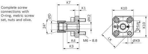
|
LK |
D |
Series 1) |
Material number |
pmax |
K1 |
K2 |
K3 |
K4 |
K7 |
K9 |
K10 |
SW |
Screws |
O-ring |
Weight |
|
mm |
mm |
bar |
mm |
mm |
mm |
mm |
mm |
mm |
mm |
mm |
4 × |
NBR |
kg |
||
| 35 | 10 | L | 1 515 702 064 | 315 | 8 | 7 | 30 | 23 | 38 | 6.5 | 40 | 19 | M6 × 22 | 20 × 2.5 | 0.13 |
| 35 | 12 | L | 1 515 702 065 | 315 | 8 | 9 | 30 | 23 | 38.5 | 6.5 | 40 | 22 | M6 × 22 | 20 × 2.5 | 0.14 |
| 35 | 15 | L | 1 515 702 066 | 250 | 8 | 11 | 30 | 23 | 39 | 6.5 | 40 | 27 | M6 × 22 | 20 × 2.5 | 0.15 |
| 40 | 15 | L | 1 515 702 067 | 100 | 8 | 11 | 35 | 28 | 44 | 6.5 | 40 | 27 | M6 × 22 | 26 × 2.5 | 0.16 |
| 40 | 18 | L | 1 515 702 068 | 100 | 8 | 14 | 35 | 27.5 | 44 | 6.5 | 40 | 32 | M6 × 22 | 26 × 2.5 | 0.17 |
| 40 | 22 | L | 1 515 702 069 | 100 | 8 | 18 | 35 | 27.5 | 45 | 6.5 | 40 | 36 | M6 × 22 | 26 × 2.5 | 0.16 |
| 40 | 28 | L | 1 515 702 008 | 100 | 8 | 19 | 35 | 27.5 | 45 | 6.5 | 40 | 41 | M6 × 22 | 26 × 2.5 | 0.18 |
| 1) | See DIN EN ISO 8434-1 |
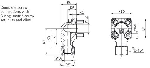
90° angle flange, for square flange 20
|
LK |
D |
Series 1) |
Material number |
pmax |
K1 |
K2 |
K3 |
K4 |
K5 |
K6 |
K7 |
K9 |
K10 |
SW |
Screws |
O-ring |
Weight |
|
|
mm |
mm |
bar |
mm |
mm |
mm |
mm |
mm |
mm |
mm |
mm |
mm |
mm |
2 × |
2 × |
NBR |
kg |
||
| 35 | 10 | L | 1 515 702 070 | 315 | 8 | 14 | 37.5 | 30.5 | 16.5 | 28.5 | 45 | 6.4 | 39 | 19 | M6 × 22 | M6 × 35 | 20 × 2.5 | 0.18 |
| 35 | 12 | L | 1 515 702 071 | 315 | 8 | 14 | 37.5 | 30.5 | 16.5 | 28.5 | 46 | 6.4 | 39 | 22 | M6 × 22 | M6 × 35 | 20 × 2.5 | 0.19 |
| 35 | 15 | L | 1 515 702 072 | 250 | 8 | 14 | 37.5 | 30.5 | 16.5 | 28.5 | 46 | 6.4 | 39 | 27 | M6 × 22 | M6 × 35 | 20 × 2.5 | 0.2 |
| 35 | 16 | S | 1 515 702 002 | 315 | 8 | 15 | 38 | 29.5 | 20 | 33 | 49 | 6.4 | 39 | 30 | M6 × 22 | M6 × 40 | 20 × 2.5 | 0.25 |
| 35 | 18 | L | 1 545 702 006 | 250 | 8 | 15 | 37.5 | 30 | 20 | 33 | 47 | 6.4 | 39 | 32 | M6 × 22 | M6 × 40 | 20 × 2.5 | 0.22 |
| 35 | 20 | S | 1 515 702 017 | 315 | 8 | 15 | 45 | 34.5 | 25 | 38 | 57 | 6.4 | 39 | 36 | M6 × 22 | M6 × 45 | 20 × 2.5 | 0.3 |
| 40 | 15 | L | 1 515 702 073 | 100 | 9 | 20 | 38 | 31 | 22.5 | 38 | 47 | 6.4 | 42 | 27 | M6 × 22 | M6 × 22 | 26 × 2.5 | 0.26 |
| 40 | 18 | L | 1 515 702 074 | 100 | 9 | 20 | 38 | 30.5 | 22.5 | 38 | 47.5 | 6.4 | 42 | 32 | M6 × 22 | M6 × 22 | 26 × 2.5 | 0.27 |
| 40 | 20 | S | 1 515 702 011 | 250 | 9 | 20 | 40 | 29.5 | 22.5 | 37 | 52 | 6.4 | 42 | 36 | M6 × 22 | M6 × 45 | 26 × 2.5 | 0.26 |
| 40 | 22 | L | 1 515 702 075 | 100 | 9 | 20 | 38 | 30.5 | 22.5 | 38 | 48 | 6.4 | 42 | 36 | M6 × 22 | M6 × 22 | 26 × 2.5 | 0.27 |
| 40 | 28 | L | 1 515 702 010 | 100 | 9 | 20 | 40 | 32.5 | 28 | 44 | 50.5 | 6.4 | 42 | 41 | M6 × 22 | M6 × 50 | 26 × 2.5 | 0.37 |
| 40 | 35 | L | 1 515 702 018 | 100 | 9 | 20 | 41 | 30.5 | 34 | 53 | 53 | 6.4 | 42 | 50 | M6 × 22 | M6 × 60 | 26 × 2.5 | 0.41 |
| 55 | 20 | S | 1 515 702 004 | 250 | 13 | 18.2 | 45 | 34.5 | 24 | 38 | 57 | 8.4 | 58 | 36 | M8 × 25 | M8 × 50 | 32 × 2.5 | 0.62 |
| 55 | 30 | S | 1 545 719 006 | 250 | 12 | 26.5 | 49 | 38.5 | 32 | 51 | 63.5 | 8.4 | 58 | 50 | M8 × 25 | M8 × 50 | 32 × 2.5 | 0.63 |
| 55 | 35 | L | 1 515 702 005 | 100 | 12 | 26.5 | 49 | 38.5 | 32 | 52 | 61 | 8.4 | 58 | 50 | M8 × 25 | M8 × 60 | 32 × 2.5 | 0.77 |
| 55 | 42 | L | 1 515 702 019 | 100 | 12 | 26.5 | 49 | 38 | 40 | 64 | 61.5 | 8.4 | 58 | 60 | M8 × 25 | M8 × 70 | 32 × 2.5 | 1.04 |
| 1) | See DIN EN ISO 8434-1 |
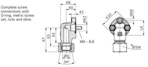
90° angle flange, 3-hole, for square flange 30
|
LK |
D |
Series 1) |
Material number |
pmax |
K1 |
K2 |
K3 |
K4 |
K5 |
K6 |
K7 |
K9 |
K10 |
SW |
Screws |
O-ring |
Weight |
|
mm |
mm |
bar |
mm |
mm |
mm |
mm |
mm |
mm |
mm |
mm |
mm |
mm |
3 × |
NBR |
kg |
||
| 30 | 12 | L | 1 515 702 146 | 250 | 9 | 12.5 | 37 | 30 | 19 | 30.5 | 46 | 6.4 | 38 | 22 | M6 × 25 | 16 × 2.5 | 0.18 |
| 30 | 15 | L | 1 515 702 147 | 250 | 9 | 12.5 | 37 | 30 | 19 | 30.5 | 45.5 | 6.4 | 38 | 27 | M6 × 25 | 16 × 2.5 | 0.2 |
| 40 | 22 | L | 1 515 702 149 | 160 | 13.5 | 19 | 43 | 35.5 | 25 | 41 | 53 | 8.4 | 48 | 36 | M8 × 30 | 24 × 2.5 | 0.4 |
| 40 | 28 | L | 1 515 702 150 | 160 | 13.5 | 19 | 43 | 35.5 | 25 | 41 | 53.5 | 8.4 | 48 | 41 | M8 × 30 | 24 × 2.5 | 0.36 |
| 1) | See DIN EN ISO 8434-1 |
Note
Permissible tightening torques can be found in the “General Operating Instructions for External Gear Units” (07012-B).
Ordering codes
Downloads


Нет отзывов об этом товаре.