
Доступно к заказу
Цена по запросу
И выбери подходящего.
Description
- Fixed displacement
- Frame size 1, 2
- Size 16 … 79
- Nominal pressure 290 bar
- Maximum pressure 320 bar
- Displacement 15.9 … 79.3 cm³
Features
- High bearing life due to hydraulically-balanced drive shaft
- Low wear due to hydraulically unloaded vanes
- Low operating noise
- Easy to service due to exchangable pump cartridges
- Good efficiency
- Position of the suction port selectable
- Drive direction of rotation clockwise or counterclockwise
- Drive shaft optionally cylinderical or splined
- Use:
For drives with high working pressure, for example, press brakes
Product description
Functional diagram
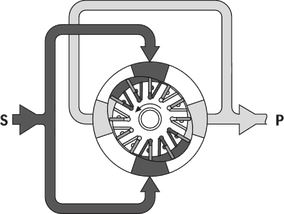
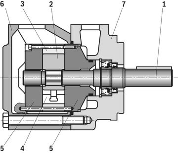
Hydraulic pumps of type PVH are vane pumps with constant displacement. The rotor (2) running in a stator ring (3) is located on the tooth profile of the drive shaft (1). The slots of the rotor accommodate the vanes (4) which are pressed against the internal surfaces of the stator ring by the centrifugal force upon rotation of the rotor. The displacer chambers are laterally sealed by the control plates (5). Due to the double-eccentric design of the stator ring, there are in each case two pressure chambers opposite of two suction chambers, which provides for hydraulic unloading of the shaft. So it only has to transmit the torque. The vanes are partially unloaded upon passage through the suction range. This unloading has a wear-reducing effect and ensures high efficiency. By simply removing the cover (6), the pump insert (consisting of rotor, vane, stator ring and control plates) can be removed without the need of removing the housing (7) from the pump carrier. This allows for fast maintenance and repair of the pump.
Section PVH
Type code
| 01 | 02 | 03 | 04 | 05 | 06 | 07 | 08 | 09 | 10 | 11 | 12 | ||
| PV | H | – | 1X | / | 15 | * |
| Type | ||||||||||||||||
| 01 | Vane pump, fixed displacement | PV | ||||||||||||||
| Series | ||||||||||||||||
| 02 | High-pressure pump | H | ||||||||||||||
| Frame size BG | ||||||||||||||||
| 03 | BG1 | 1 | ||||||||||||||
| BG2 | 2 | |||||||||||||||
| Series | ||||||||||||||||
| 04 | Series 10 to 19 (10 to 19: unchanged installation and connection dimensions) | 1X | ||||||||||||||
| Size (NG) | 016 | 020 | 023 | 025 | 028 | 032 | 035 | 041 | 045 | 050 | 058 | 064 | 070 | 079 | ||
| 05 | Frame Size 1 | ● | ● | ● | ● | ● | ● | ● | – | – | – | – | – | – | – | |
| Frame Size 2 | ● | ● | ● | ● | ● | ● | ● | ● | ● | ● | ● | ● | ● | ● | ||
| Direction of rotation | ||||||||||||||||
| 06 | Viewed on drive shaft | right | R | |||||||||||||
| counterclockwise | L | |||||||||||||||
| Drive shaft | ||||||||||||||||
| 07 | Cylindrical shaft with fitting key DIN 6885 | A | ||||||||||||||
| Splined shaft SAE J744 with involute tooth system according to ANSI B92.1a | J | |||||||||||||||
| Line connection | ||||||||||||||||
| 08 | Suction and pressure port according to SAE J518; standard pressure series | 15 | ||||||||||||||
| Location of the suction port (with a view toward the drive shaft) | ||||||||||||||||
| 09 | Above (0° from pressure port) | D | ||||||||||||||
| Below (180° from pressure port) | U | |||||||||||||||
| Right (90° to the right of pressure port) | R | |||||||||||||||
| Left (90° to the left of pressure port) | L | |||||||||||||||
| Seal material | ||||||||||||||||
| 10 | NBR (nitrile rubber) | M | ||||||||||||||
| FKM (fluor-caoutchouc) | V | |||||||||||||||
| Mounting flange | ||||||||||||||||
| 11 | 101-2 (SAE-B) | B | ||||||||||||||
| Others upon request | * | |||||||||||||||
| Additional details | ||||||||||||||||
| 12 | Information in the plain text | * | ||||||||||||||
| ● = Available – = Not available |
Technical data
| Frame size |
| 1 | 2 | |||||||||||||||||||||
| Size |
| 16 | 20 | 23 | 25 | 28 | 32 | 35 | 16 | 20 | 23 | 25 | 28 | 32 | 35 | 41 | 45 | 50 | 58 | 64 | 70 | 79 | ||
| Component series |
| 1X | ||||||||||||||||||||||
| Mounting type |
| Flange mounting | ||||||||||||||||||||||
| Drive speed 1) | n |
rpm | 600 ... 3.600 | 600 ... 30 | 600 ... 3.600 | 600 ... 30 | 600 ... 2.800 | 600 ... 2.500 | ||||||||||||||||
| Displacement | Vg |
cm³ | 15.9 | 19.8 | 22.5 | 24.9 | 28 | 31.8 | 35 | 15.9 | 19.8 | 22.5 | 24.9 | 28 | 31.8 | 35 | 41 | 45 | 50 | 58.3 | 63.8 | 70.3 | 79.3 | |
| Flow, max. 2) | qV |
l/min | 23.5 | 29.3 | 33.2 | 36.8 | 41.4 | 47 | 51.7 | 23.5 | 29.3 | 33.2 | 36.8 | 41.4 | 47 | 51.7 | 60.6 | 66.5 | 73.9 | 86.1 | 94.3 | 103.9 | 117 | |
| Operating pressure, absolute | continuous 3) | pN |
bar | 290 | 270 | 290 | 270 | 240 | ||||||||||||||||
| intermittent | pmax |
bar | 320 | 300 | 320 | 300 | 275 | |||||||||||||||||
| Weight | m |
kg | 23 | |||||||||||||||||||||
| 1) | The values apply at absolute pressure pabs = 1 bar at suction port S. |
| 2) | at 1500 rpm |
| 3) | The values apply for HLP mineral oil according to DIN 51524 Part 2 |
Hydraulic fluid
| Permissible hydraulic fluid | Mineral oil HLP according to DIN 51524 part 2 | |
| Special fluid | Flame-resistant water-free hydraulic fluid HFD according to ISO 12922 Water polymer solutions HFC according to ISO 12922 (reduced operating pressure 175/140 bar) Observe our application notes and application requirements in the data sheets 90220 (HLP), 90222 (HFD) and 90223 (HFC). | |
| Hydraulic fluid temperature range 1) | °C | -10 … +80 |
| Viscosity range 2) | mm²/s | 13 … 54 |
| Maximum admissible degree of contamination of the hydraulic fluid 3) | Class 20/18/15 according to ISO 4406 (c) |
| 1) | +30 … +60 °C recommended (as per viscosity range) |
| 2) | 54 ... 860 mm/s2 with 50 % of pressure and only at the start |
| 3) | The cleanliness classes specified for the components must be adhered to in hydraulic systems. Effective filtration prevents faults and simultaneously increases the life cycle of the components. For the selection of the filters, see www.boschrexroth.com/filter. |
Diagrams/characteristic curves
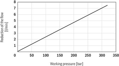
Flow loss, pressure-dependent (measured with ν = 41 mm2/s; ϑ = 50 °C)
Symbols/Circuit diagrams

Dimensions
Dimensions frame sizes 1 and 2
Dimensions in mm
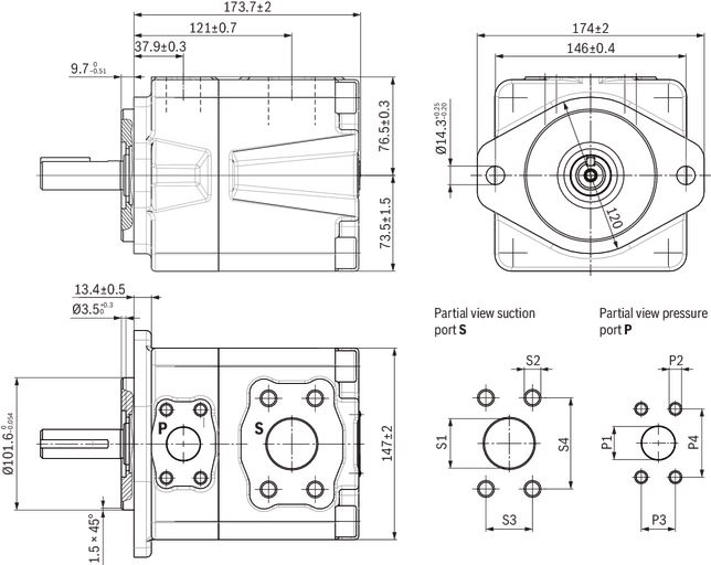
Ports according to SAE J518
|
| Suction port | Pressure port | ||||||||
| S | S1 | S2 | S3 | S4 | P | P1 | P2 | P3 | P4 | |
| in | mm | mm | mm | in | mm | mm | mm | |||
| BG1 | 1 1/4 | 31,8 | 7/16 in - 14 UNC; 24 mm deep | 30,2 | 58,7 | 3/4 | 19,1 | 3/8 in - 16 UNC; 21 mm deep | 22,2 | 47,6 |
| BG2 | 1 1/2 | 38,1 | 1/2 in - 13 UNC; 24 mm deep | 35,7 | 69,9 | 1 | 25,5 | 3/8 in - 16 UNC; 21 mm deep | 26,2 | 52,4 |
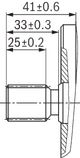
Cylindrical shaft with fitting key, DIN 6885, 6.35 x 38
A
Dimensions in mm
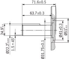
Splined shaft SAE J744
J - 7/8 in 13T 16/32DP1)
Dimensions in mm
| 1) | Involute tooth system according to ANSI B92.1a, 30° pressure angle, flat root, side fit, tolerance class 5 |
SAE connection flanges
Dimensions in mm
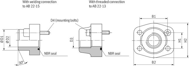
| PVH | Flange | Material number1) for flange with | B1 | B2 | H1 | H2 | D1 | D2 | D3 | D4 | ||
| Suction flange | Pressure flange | NG, pressure | Welded connection | Threaded connection 2) | ||||||||
| mm | mm | mm | mm | mm | mm | |||||||
| - | BG1 | 3/4 in 3000 psi | Upon request | R900063050 | 47,6 | 65 | 22,2 | 52 | 25 | 19 | G3/4 | 3/8 in - 16 UNC |
| - | BG2 | 1 in 3000 psi | Upon request | R9002111753) | 52,4 | 70 | 26,2 | 59 | 30 | 22 | G1 | 3/8 in - 16 UNC |
| BG1 | - | 1 1/4 in 3000 psi | R900211363 | R900211172 | 58,7 | 79 | 30,2 | 68 | 38 | 28 | G1 1/4 | 7/16 in - 14 UNC |
| BG2 | - | 1 1/2 in 3000 psi | R900211168 | R900211171 | 69,9 | 95 | 35,7 | 76 | 38 | 30 | G1 1/2 | 1/2 in - 13 UNC |
| 1) | The material numbers comprise the flange, the O-ring (NBR) and the mounting screws. |
| 2) | Pipe thread “G” according to DIN EN ISO 228-1 |
| 3) | For sizes 16 to 32, the maximum working pressure for this connection flange of 315 bar must be observed. |
Project planning information
General project planning notes
Intended use
Vane pumps are intended for the assembly of hydraulic drive systems in machine and system construction.
Technical data
The system or machine manufacturer must ensure compliance with the permissible technical data and operating conditions. The pump itself does not contain a device to prevent operation outside the permissible data. It is possible to operate the pump outside of the permissible technical data to a certain extent; the express written consent from Bosch Rexroth is, however, required. All specified technical performance features are median values and apply with the specified general conditions. In case of modifications to the general conditions (e.g., viscosity), the technical data may change as well. Scatter corresponding to the relevant state of technology is possible.
Hydraulic project planning
Air bleeding option for commissioning
For Rexroth PVH vane pumps, a manual or switchable air bleeding option for the initial commissioning or any recommissioning after maintenance and repair work is to be provided. The air bleeding point is to be set in the pressure line before the first valve or check valve. Air bleeding may be performed with a maximum counter pressure of 0,2 bar.
Examples of air bleeding circuits
Switchable bleeding
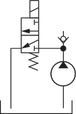
Manually operated bleeding

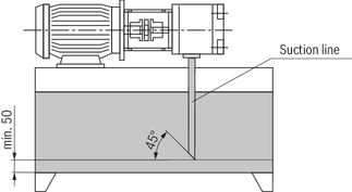
Suction line
The line cross sections are to be dimensioned for the specified flows such that an ideal suction speed of 0,6 to 0,6 m/s is achieved on average. The suction speed should not exceed a maximum value of 2 m/s.
The suction cross sections at the pump itself are designed for the maximum flow and therefore serve only as reference. In case of continuous operation at rotational speeds lower than the permissible maximum speed, the suction tube diameter is also to be dimensioned smaller than the suction port of the pump depending on the actual suction speed.
Overall, the suction line is to be designed so that the permissible inlet working pressure is maintained. Bends and a combination of suction pipes from several pumps are to be avoided. If the use of a suction filter is unavoidable, it must be ensured on the system side that the lowest permissible inlet working pressure is not exceeded even if the filter is contaminated.
Ensure the air tightness of the transitions and the pressure resistance of the suction hose with respect to the external air pressure.
The immersion depth of the suction pipe should be selected as large as possible (at least 100 mm at the lowest fluid level). Depending on the internal reservoir pressure, the viscosity of the operating medium and the flow conditions within the reservoir, no vortex may form even at maximum flow. There is otherwise a risk of air being drawn in. Return fluid and case drain fluid must not be immediately be drawn in again.
Dimensions in mm
Pressure line
Sufficient burst resistance of the pipes, hoses and connecting elements must be ensured for pressure lines. The cross sections should be based on the maximum flow in order to avoid additional excessive loading of the pump due to back-pressure. Here, you must also take into account the pipe losses over the entire pressure line length and other line resistances (e.g., bends, pressure filters).
Pressure safeguarding
The PVH vane pump does not include any devices for adherence to the maximum working pressure. The setting and safeguarding of the permissible working pressure must be ensured on the system side.
The pressure-relief valves necessary for this purpose are to be designed with consideration given to the maximum flow and the rate of pressure increase that will occur such that the permissible intermittent working pressure is not exceeded.
Mounting
Mechanical project planning
Fastening
The screws must be accessible on the machine-side so that the required tightening torque can be applied. The tightening torque of the screws is based on the operating conditions and involved elements of the screw connection and must be specified by the manufacturer in the power unit, machine or system project planning.
Tank
In the tank construction or the selection of suitable standard tanks, the following requirements are to be observed:
- Selection of the largest tank volume possible, dependent on the permanent or average flow, in order to allow for the separation of air bubbles by means of sufficient duration time of the medium in the tank. The air release capacity of the hydraulic fluid used is also of importance.
- Provision of settling zones for the hydraulic fluid in the tank in order to allow for air release.
- Provision of guiding plates in order to allowing for the deposit of contamination at the tank bottom outside the pump suction area.
- Large dimensioning of the tank surfaces dependent on the heat output to be dissipated via the tank walls.
Required power unit functions
Hydraulic power units should at least be equipped with the following features:
- Tanks, where internal pressure corresponds to the ambient pressure in accordance with the design, must be equipped with breathing filters for pressure compensation purposes.
- The hydraulic fluid should only be filled in using filling connections excluding filling with unfiltered fluid.
- The ingress of contamination or humidity must be avoided. In case of use in highly contaminated environments, the tank must to this end be pre-tensioned by means of air pressure. If cleansing of the external tank side is intended or to be expected during the period of use, select tank fittings for pipes, lines, or hoses, which ensure safe sealing against external pressurization with water jet.
Place of installation and environmental conditions
With places of installation from a geodetic height of more than 1000 m, the pump is to be arranged in or below the tank or the tank is to be pre-tensioned by means of compressed air in order to comply with the admissible minimum inlet pressure. A short suction line with large cross-section must be selected, bends should not be used.
When installing the pump more than 10 m below the tank, the reduction of the inlet pressure to the maximum admissible value must be ensured by means of additional measures.
When operating the pump in salt-containing or corrosive environments or when pressure loading with strongly abrasive substances is possible, make sure on the system side that the shaft seal ring and the sealing area of the shaft do not make direct contact with the environment.
Drive
Electric motor + pump carrier + coupling + pump
- No radial and axial forces on the pump drive shaft admissible!
- Motor and pump must be exactly aligned!
- Always use a coupling that is suitable for compensating shaft displacements!
Installation positions
B3
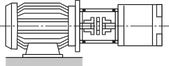
B5
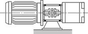
V1
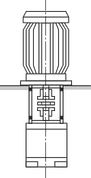
Maintenance
Maintenance schedule and operational safety
For safe operation and a long service life of the pump, a maintenance schedule must be prepared for the power unit, the machine, or the system. The maintenance schedule must ensure that the specified or permissible operating conditions of the pump are complied with over the entire period of use.
In particular, compliance with the following operating parameters has to be ensured:
- The required oil cleanliness
- The operating temperature range
- The filling level of the operating medium
Furthermore, the pump and the system are to be checked for changes to the following parameters on a regular basis:
- Vibrations
- Noise
- Temperature difference between pump – fluid in the reservoir
- Foaming in the reservoir
- Leak-proofness
Changes to these parameters indicate component wear (e.g., drive motor, coupling, pump, etc.). The cause has to be determined and remedied immediately. In order to achieve high operational safety of the pump in the machine or system, we recommend checking the aforementioned parameters continuously and automatically and the automatic shut-down in case of changes exceeding the usual fluctuations in the specified operating range.
Plastic components of drive couplings should be replaced regularly, though after no more than 5 years. The corresponding manufacturer's specifications are paramount. For preventive maintenance of the pump, we recommend having the seals replaced after an operating period of no more than 5 years by an authorized Bosch Rexroth service company.
Accessories
Pump safety block
For limiting the working pressure and for the pump circulation at zero pressure, we recommend our pump safety blocks. Automatic air bleeding during commissioning is, however, not possible via DBA blocks. In this case, we recommend separate, manual air bleeding.
Pump safety block
DBA…1X
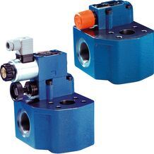
Pump safety block
DBA…1X
- Size 32, 40
- Component series 1X
- Maximum operating pressure 350 bar
- Maximum flow 650 l/min
Pump safety block
DBA, DBAW…1X
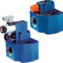
Pump safety block
DBA, DBAW…1X
- Size 32, 40
- Component series 1X
- Maximum operating pressure 350 bar
- Maximum flow 650 l/min
Pump safety block
DBA...2X
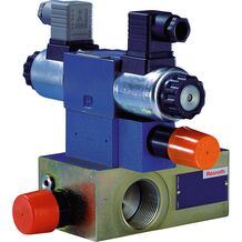
Pump safety block
DBA...2X
- Size 16 … 32
- Component series 2X
- Maximum operating pressure 350 bar
- Maximum flow 400 l/min
Pump safety block
DBAW...2X
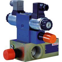
Pump safety block
DBAW...2X
- Size 16 … 32
- Component series 2X
- Maximum operating pressure 350 bar
- Maximum flow 400 l/min
Pump safety block
DBAE...2X
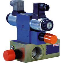
Pump safety block
DBAE...2X
- Size 16 … 32
- Component series 2X
- Maximum operating pressure 350 bar
- Maximum flow 400 l/min
Pump safety block
DBAEE...2X
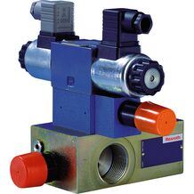
Pump safety block
DBAEE...2X
- Size 16 … 32
- Component series 2X
- Maximum operating pressure 350 bar
- Maximum flow 400 l/min
Pump safety block
DBAEA...2X
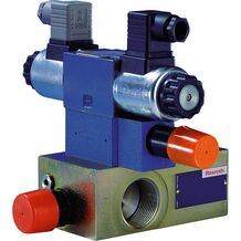
Pump safety block
DBAEA...2X
- Size 16 … 32
- Component series 2X
- Maximum operating pressure 350 bar
- Maximum flow 400 l/min
Safety Instructions
Pump safety block
For limitation of the working pressure or (and) for solenoidactuated relief of working pressure we recommend our pump-pressure-safety-block to data sheets 25880 and 25891.
Ordering codes
Downloads
 | Fixed displacement vane pump, PVH Series 1X Data Sheet | RE10338 | 2015-05-31 | English | PDF | 277k Product Groups: Vane pumps |

Нет отзывов об этом товаре.