
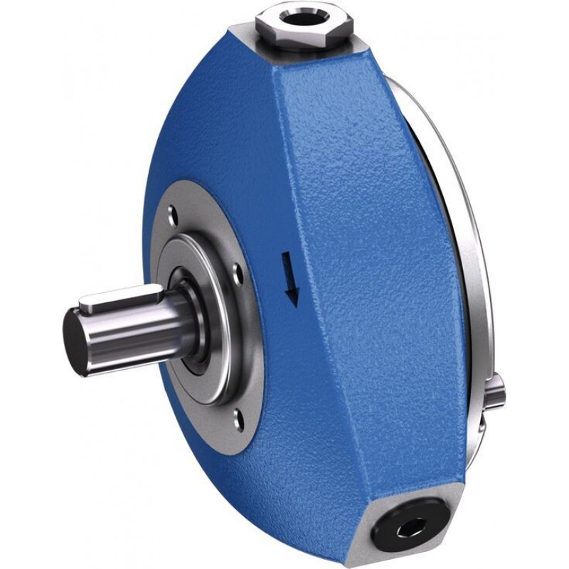
Доступно к заказу
Цена по запросу
И выбери подходящего.
Description
- Size 1,60 … 20,00
- Component series 3X
- Maximum operating pressure 700 bar
- Maximum displacement 19.43 cm³
Features
- Fixed displacement
- Self-priming, valve-controlled
- Long service life due to hydro-dynamically lubricated plain bearings
- Several pressure ports with different cylinder combinations
- 14 sizes, favorable grading for perfect device design
Product description
Assembly
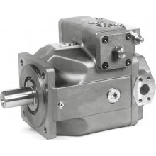
The pumps are valve-controlled, self-priming radial piston pumps with fixed displacement.
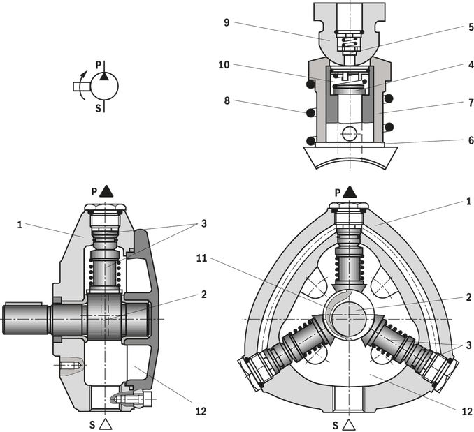
They consist essentially of the housing (1), eccentric shaft (2) and 3, 5 or 10 pump elements (3), with suction valve (4), pressure valve (5) and piston (6).
Suction and displacement procedure
The pistons (6) are arranged radially to the eccentric shaft (2). The hollow piston (6) with the suction valve (4) is guided in a cylinder (7) and pressed onto the eccentric (2) by the spring (8). The radius of the piston running surface corresponds to the eccentric radius. The cylinder (7) provides sealing against a hemispherical element (9).
In downward movements of the piston (6), the working space (10) in the cylinder (7) is enlarged. Due to the resulting negative overpressure, the suction valve plate is raised from the sealing lip. Simultaneously, the connection from the suction chamber (12) to the working chamber (10) is realized by means of a radial groove (11) in the eccentric (2).
The working chamber is filled with fluid. In upward movements of the piston (6), the suction valve (4) is closed and the pressure valve (5) is opened. The fluid now flows to the system via the pressure port (P).
Type code
| 01 | 02 | 03 | 04 | 05 | 06 | 07 | 08 | 09 | ||
| PR4 | – | 3X | / | R | * |
| Type | ||||
| 01 | Radial piston pump, fixed displacement, maximum pressure 700 bar | PR4 | ||
| Component series | ||||
| 02 | Component series 30 ... 39 (30 ... 39: unchanged installation and connection dimensions) | 3X | ||
| Size | NG | Pressure rating |
| |
| 03 | Size – pressure stage (maximum) | 1,60 | 700 bar | 1,60-700 |
| 2,00 | 700 bar | 2,00-700 | ||
| 2,50 | 700 bar | 2,50-700 | ||
| 3,15 | 700 bar | 3,15-700 | ||
| 4,00 | 700 bar | 4,00-700 | ||
| 6,30 | 700 bar | 6,30-700 1) | ||
| 8,00 | 700 bar | 8,00-700 1) | ||
| 3,15 | 500 bar | 3,15-500 | ||
| 5,00 | 500 bar | 5,00-500 | ||
| 6,30 | 500 bar | 6,30-500 | ||
| 8,00 | 500 bar | 8,00-500 | ||
| 10,00 | 500 bar | 10,00-500 | ||
| 16,00 | 500 bar | 16,00-500 1) | ||
| 20,00 | 500 bar | 20,00-500 2) | ||
| Direction of rotation | ||||
| 04 | Viewed on drive shaft | clockwise | R | |
| Drive shaft | ||||
| 05 | Parallel keyed shaft | A | ||
| Splined shaft 21 x 24, DIN 5481 | G | |||
| Cylindrical shaft with output for mounting an AZPF or AZPFF | K | |||
| Line connection | ||||
| 06 | Pipe thread according to ISO 228/1 | 01 | ||
| SAE thread to ANSI B1.1 | 12 | |||
| Seal material | ||||
| 07 | NBR seals | M | ||
| FKM seals | V | |||
| Pressure ports | ||||
| 08 | 1 Pressure port | 01 | ||
| 2 Pressure ports | 02 | |||
| 3 Pressure ports | 03 | |||
| 5 Pressure ports | 08 | |||
| 6 Pressure ports | 11 | |||
| 10 Pressure ports | 12 | |||
| Additional details | ||||
| 09 | Further details in the plain text | * | ||
| 1) | Not available with shaft versions "G" and "K" |
| 2) | Not available with shaft versions "K" |
Design options with multi-circuit pumpsThe following can be seen from the following schematic representations:
Points mark the cylinders which are directly located at the pressurized pressure port. Circles mark the cylinders which are not directly located at the pressurized pressure port. The dashed and/or dot and dash lines show which cylinders are in each case combined. The pressurized pressure ports are designated in clockwise direction. The pressure port that - in clockwise direction - is closest to the suction port is referred to as P1 . | ||||
| Type code (Pos. 08) | Number of pressure ports | Combination of cylinders | ||
| 3 pistons | 5 pistons | 10 pistons | ||
| 01 | 1 | 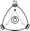 | 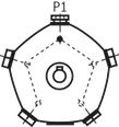 | 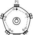 |
| 02 | 2 | 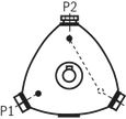 | 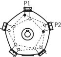 | |
| 03 | 3 | 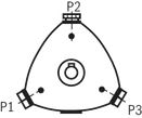 | ||
| 08 | 5 | 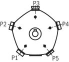 | 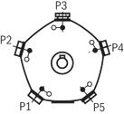 | |
| 11 | 6 | 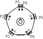 | ||
| 12 | 10 | 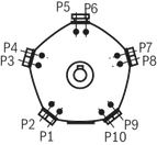 | ||
| 01 | 02 | 03 | 04 | 05 | 06 | 07 | 08 | 09 | 10 | 11 | |||
| R4 | – | 3X | / | R | K | M | + | * |
| Pump combinations | ||||
| 01 | 2-fold | P2 | ||
| 3-fold | P3 | |||
| Type | ||||
| 02 | Radial piston pumps, fixed displacement | R4 | ||
| Component series | ||||
| 03 | Component series 30 ... 39 (30 ... 39: unchanged installation and connection dimensions) | 3X | ||
| Size | NG | Pressure rating |
| |
| 04 | Size – pressure stage (maximum) | 1,60 | 700 bar | 1,60-700 |
| 2,00 | 700 bar | 2,00-700 | ||
| 2,50 | 700 bar | 2,50-700 | ||
| 3,15 | 700 bar | 3,15-700 | ||
| 4,00 | 700 bar | 4,00-700 | ||
| 3,15 | 500 bar | 3,15-500 | ||
| 5,00 | 500 bar | 5,00-500 | ||
| 6,30 | 500 bar | 6,30-500 | ||
| 8,00 | 500 bar | 8,00-500 | ||
| 10,00 | 500 bar | 10,00-500 | ||
| Direction of rotation | ||||
| 05 | Viewed on drive shaft | clockwise | R | |
| Drive shaft | ||||
| 06 | Cylindrical shaft with output for mounting an AZPF or AZPFF | K | ||
| Line connection | ||||
| 07 | Pipe thread according to ISO 228/1 | 01 | ||
| SAE thread to ANSI B1.1 | 12 | |||
| Seal material | ||||
| 08 | NBR seals | M | ||
| Pressure ports | ||||
| 09 | 1 Pressure port | 01 | ||
| 2 Pressure ports | 02 | |||
| 3 Pressure ports | 03 | |||
| 5 Pressure ports | 08 | |||
| Combination pumps | ||||
| 10 | 2-fold | NG |
| |
| 4 cm3 | AZPF4 | |||
| 5 cm3 | AZPF5 | |||
| 8 cm3 | AZPF8 | |||
| 11 cm3 | AZPF11 | |||
| 14 cm3 | AZPF14 | |||
| 16 cm3 | AZPF16 | |||
| 19 cm3 | AZPF19 | |||
| 22 cm3 | AZPF22 | |||
| 25 cm3 | AZPF25 | |||
| 28 cm3 | AZPF28 | |||
| 3-fold | NG |
| ||
| 5 cm3 - 4 cm3 | AZPFF5-4 | |||
| 8 cm3 - 4 cm3 | AZPFF8-4 | |||
| 8 cm3 - 8 cm3 | AZPFF8-8 | |||
| 11 cm3 - 4 cm3 | AZPFF11-4 | |||
| 11 cm3 - 5 cm3 | AZPFF11-5 | |||
| 11 cm3 - 8 cm3 | AZPFF11-8 | |||
| 16 cm3 - 8 cm3 | AZPFF16-8 | |||
| 16 cm3 - 16 cm3 | AZPFF16-16 | |||
| Additional details | ||||
| 11 | Further details in the plain text | * | ||
| 1) | Project planning information for multiple pumps has to be observed |
Technical data
| Size | 1,60 | 2,00 | 2,50 | 3,15 | 4,00 | 6,30 | 8,00 | 3,15 | 5,00 | 6,30 | 8,00 | 10,00 | 16,00 | 20,00 | |||||
| Displacement | geometric | Vg | cm³ | 1.51 | 2.14 | 2.59 | 3.57 | 4.32 | 7.14 | 8.63 | 3.39 | 4.82 | 5.83 | 8.03 | 9.71 | 16.07 | 19.43 | ||
| Drive speed | nmin | rpm | 1000 | 1000 | 1000 | 1000 | 1000 | 1000 | 1000 | 1000 | 1000 | 1000 | 1000 | 1000 | 1000 | 1000 | |||
| nmax | rpm | 2000 | 2000 | 2000 | 2000 | 2000 | 2000 | 2000 | 2000 | 2000 | 2000 | 2000 | 2000 | 2000 | 2000 | ||||
| Operating pressure | absolute | Inlet | p | bar | 0.8 ... 2.5 | 0.8 ... 2.5 | 0.8 ... 2.5 | 0.8 ... 2.5 | 0.8 ... 2.5 | 0.8 ... 2.5 | 0.8 ... 2.5 | 0.8 ... 2.5 | 0.8 ... 2.5 | 0.8 ... 2.5 | 0.8 ... 2.5 | 0.8 ... 2.5 | 0.8 ... 2.5 | 0.8 ... 2.5 | |
| Outlet | continuous | pN | bar | 700 | 700 | 700 | 700 | 700 | 700 | 700 | 500 | 500 | 500 | 500 | 500 | 500 | 500 | ||
| Inner diameter of the cylinders | Ø | mm | 10 | 10 | 10 | 10 | 10 | 10 | 10 | 15 | 15 | 15 | 15 | 15 | 15 | 15 | |||
| Torque | max. | Drive shaft | Nm | 160 | 160 | 160 | 160 | 160 | 160 | 160 | 160 | 160 | 160 | 160 | 160 | 160 | 160 | ||
| Number of cylinders | 3 | 3 | 3 | 5 | 5 | 10 | 10 | 3 | 3 | 3 | 5 | 5 | 10 | 10 | |||||
| Weight | m | kg | 9.2 | 9.2 | 9.2 | 12.4 | 12.4 | 16.4 | 16.4 | 9.2 | 9.2 | 9.2 | 12.4 | 12.4 | 16.4 | 16.4 | |||
| Drive shaft loading | Radial and axial forces cannot be absorbed! | Radial and axial forces cannot be absorbed! | Radial and axial forces cannot be absorbed! | Radial and axial forces cannot be absorbed! | Radial and axial forces cannot be absorbed! | Radial and axial forces cannot be absorbed! | Radial and axial forces cannot be absorbed! | Radial and axial forces cannot be absorbed! | Radial and axial forces cannot be absorbed! | Radial and axial forces cannot be absorbed! | Radial and axial forces cannot be absorbed! | Radial and axial forces cannot be absorbed! | Radial and axial forces cannot be absorbed! | Radial and axial forces cannot be absorbed! | |||||
| Mounting type | Front face mounting | Front face mounting | Front face mounting | Front face mounting | Front face mounting | Front face mounting | Front face mounting | Front face mounting | Front face mounting | Front face mounting | Front face mounting | Front face mounting | Front face mounting | Front face mounting | |||||
| Line connections | Screw-in fittings | Screw-in fittings | Screw-in fittings | Screw-in fittings | Screw-in fittings | Screw-in fittings | Screw-in fittings | Screw-in fittings | Screw-in fittings | Screw-in fittings | Screw-in fittings | Screw-in fittings | Screw-in fittings | Screw-in fittings | |||||
| Direction of rotation, viewed on drive shaft | clockwise | clockwise | clockwise | clockwise | clockwise | clockwise | clockwise | clockwise | clockwise | clockwise | clockwise | clockwise | clockwise | clockwise | |||||
| Hydraulic fluid | |||||||||||||||||||
| Permissible hydraulic fluid 1) | Mineral oil (HLP) to DIN 51524-2 | ||||||||||||||||||
| Operating temperature range | °C | -10 … +70 | |||||||||||||||||
| Viscosity range | mm²/s | 10 … 200 | |||||||||||||||||
| Maximum admissible degree of contamination of the hydraulic fluid 1) | Class 20/18/15 according to ISO 4406 (c) | ||||||||||||||||||
| 1) | The cleanliness classes specified for the components must be adhered to in hydraulic systems. Effective filtration prevents faults and simultaneously increases the life cycle of the components. For the selection of the filters, see www.boschrexroth.com/filter. |
| Flow/drive power 1) | ||||||||||||||||||
| Inner diameter of the cylinders mm | Stroke mm | Vg cm3 | Pressure | bar | 50 | 100 | 150 | 200 | 250 | 300 | 350 | 400 | 450 | 500 | 550 | 600 | 650 | 700 |
| 10 | 6.4 | 0.51 | qV, eff | l/min | 0.71 | 0.7 | 0.69 | 0.69 | 0.69 | 0.685 | 0.68 | 0.68 | 0.675 | 0.67 | 0.67 | 0.665 | 0.66 | 0.66 |
| PA | kW | 0.093 | 0.164 | 0.231 | 0.29 | 0.358 | 0.42 | 0.481 | 0.54 | 0.605 | 0.67 | 0.739 | 0.81 | 0.888 | 0.97 | |||
| 10 | 9.1 | 0.71 | qV, eff | l/min | 1.02 | 1.01 | 1.0 | 0.995 | 0.99 | 0.985 | 0.98 | 0.975 | 0.97 | 0.965 | 0.96 | 0.955 | 0.95 | 0.94 |
| PA | kW | 0.129 | 0.23 | 0.328 | 0.41 | 0.503 | 0.58 | 0.677 | 0.77 | 0.856 | 0.94 | 1.046 | 1.16 | 1.257 | 1.36 | |||
| 10 | 11.0 | 0.86 | qV, eff | l/min | 1.22 | 1.21 | 1.205 | 1.2 | 1.195 | 1.19 | 1.184 | 1.18 | 1.174 | 1.17 | 1.163 | 1.157 | 1.147 | 1.14 |
| PA | kW | 0.15 | 0.275 | 0.392 | 0.49 | 0.594 | 0.70 | 0.804 | 0.91 | 1.018 | 1.13 | 1.244 | 1.37 | 1.486 | 1.61 | |||
| 15 | 6.4 | 1.13 | qV, eff | l/min | 1.6 | 1.59 | 1.58 | 1.567 | 1.56 | 1.556 | 1.546 | 1.54 | 1.53 | 1.523 | – | – | – | – |
| PA | kW | 0.213 | 0.40 | 0.547 | 0.7 | 0.85 | 1 | 1.14 | 1.27 | 1.433 | 1.566 | – | – | – | – | |||
| 15 | 9.1 | 1.61 | qV, eff | l/min | 2.28 | 2.26 | 2.25 | 2.24 | 2.23 | 2.22 | 2.20 | 2.19 | 2.18 | 2.17 | – | – | – | – |
| PA | kW | 0.27 | 0.49 | 0.71 | 0.91 | 1.11 | 1.31 | 1.51 | 1.70 | 1.91 | 2.12 | – | – | – | – | |||
| 15 | 11.0 | 1.94 | qV, eff | l/min | 2.74 | 2.73 | 2.71 | 2.7 | 2.68 | 2.67 | 2.65 | 2.64 | 2.62 | 2.6 | – | – | – | – |
| PA | kW | 0.32 | 0.57 | 0.826 | 1.06 | 1.31 | 1.55 | 1.80 | 2.05 | 2.29 | 2.53 | – | – | – | – | |||
| 1) | Mean values measured at n = 1450 rpm, Θ = 50 °C |
Uniformity coefficient f relative to n = 1450 rpm
The values from "Flow/drive power" table relate to 1 cylinder each.
To determine the required drive power, multiply the specified value by the number of cylinders.
The uniformity coefficient f should be taken into account.
| Radial piston pump (specifications apply for a frequency of 50 Hz) | |||
| 3 cylinders | 5 or 10 cylinders | ||
| Loaded cylinder | Factor f | Loaded cylinder | Factor f |
| 1 | 3.13 | 1 | 3.13 |
| 1+2 | 1.89 | ||
| 1+2 | 1.57 | 1+3 | 1.57 |
| 1+2+3 | 1.60 | ||
| 1+3+4 | 1.35 | ||
| 1+2+3+4 | 1.30 | ||
| 1+2+3 | 1 | 1+2+3+4+5 | 1 |
 |  | ||
| At pumps with 10 cylinders, 2 cylinders each are switched at a pressure port. | |||
▼ Example: Pump PR4–3X/1,60–700RA01M02
Port 1 and 2 are connected together and loaded with 450 bar, 3 is circulating at zero pressure.
PA = 2 × 0.605 kW = 1.21 kW
f = 1.57
Perf = 1.21 kW × 1.57 = 1.90 kW
Port 3 loaded with 300 bar, 1 and 2 run without pressure.
PA = 1 × 0.42 kW = 0.42 kW
f = 3.13
Perf = 0.42 kW × 3.13 = 1.31 kW
Port 1, 2 and 3, each loaded with 200 bar.
PA = 3 × 0.29 kW = 0.87 kW
f = 1
Perf = 0.87 kW × 1 = 0.87 kW
Diagrams/characteristic curves
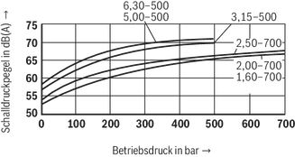
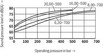
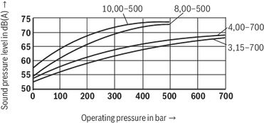
Sound pressure level (average):
(measured at n = 1450 min-1, v = 41 mm2/s and ϑ = 50 °C in a sound measuring chamber according to DIN 45635, part 26, Distance microphone – pump = 1 m)
The characteristic curves do not apply for versions with multiple circuits.
3-piston pump
5-piston pump
10-piston pump
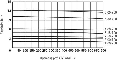
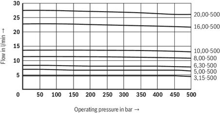
Characteristic curves – Flow:
(measured at n = 1450 min-1, v = 41 mm2/s and ϑ = 50 °C)
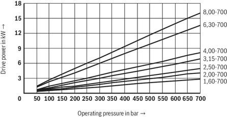
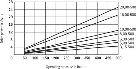
Characteristic curves – Drive power:
(measured at n = 1450 min-1, v = 41 mm2/s and ϑ = 50 °C)
Dimensions
Radial piston pump with 3 pistons
Dimensions in mm
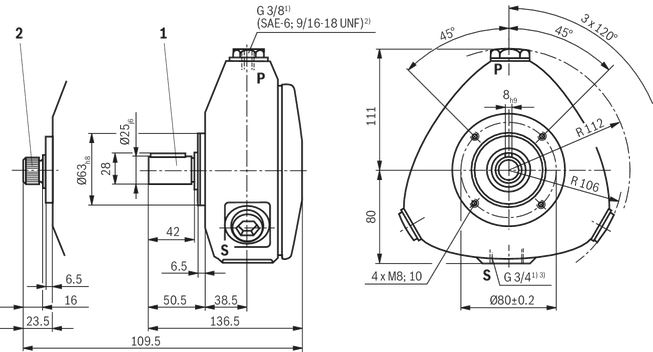
| 1) | Pipe thread according to ISO 228/1 |
| 2) | With line connection with characteristic 12, according to ANSI B 1.1 |
| 3) | With line connection with characteristic 12, connection adapter (SAE-12; 1 1/16-12 UN) according to ANSI B 1.1 not included in the scope of delivery |
Radial piston pump with 5 pistons
Dimensions in mm
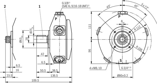
| 1) | Pipe thread according to ISO 228/1 |
| 2) | With line connection with characteristic 12, according to ANSI B 1.1 |
| 3) | With line connection with characteristic 12, connection adapter (SAE-12; 1 1/16-12 UN) according to ANSI B 1.1 not included in the scope of delivery |
- Cylindrical shaft end
- Shaft end with serration according to DIN 5481
Radial piston pump with 10 pistons
Characteristic 01, 02 and 08
Dimensions in mm
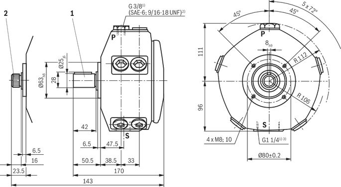
| 1) | Pipe thread according to ISO 228/1 |
| 2) | With line connection with characteristic 12, according to ANSI B 1.1 |
| 3) | With line connection with characteristic 12, connection adapter (SAE-20; 1 5/8-20 UN) according to ANSI B 1.1 not included in the scope of delivery |
- Cylindrical shaft end
- Shaft end with serration according to DIN 5481
Radial piston pump with 10 pistons
Characteristic 11 and 12
Dimensions in mm
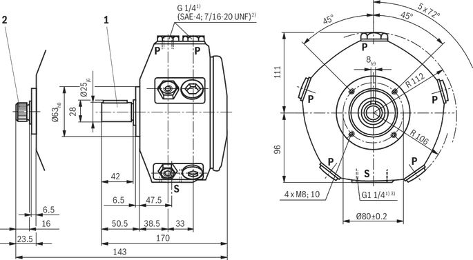
| 1) | Pipe thread according to ISO 228/1 |
| 2) | With line connection with characteristic 12, according to ANSI B 1.1 |
| 3) | With line connection with characteristic 12, connection adapter (SAE-20; 1 5/8-20 UN) according to ANSI B 1.1 not included in the scope of delivery |
- Cylindrical shaft end
- Shaft end with serration according to DIN 5481
Pump combination P2R4...
Other dimension see Dimensional drawings of PR4
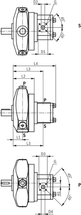
| L1 | mm | 38.5 | |||||||||
| L2 | mm | 86.8 | |||||||||
| L3 | mm | 124.2 | 125.4 | 127.5 | 131.3 | 131.8 | 139.4 | 147.5 | 148.1 | ||
| L4 | mm | 170.5 | 173 | 177.1 | 182.1 | 187.1 | 190.5 | 195.5 | 200.9 | 217.3 | 222.1 |
| Ø D1 | mm | 40 | 55 | ||||||||
| mm | ± 0.15 | ||||||||||
| Ø D2 | mm | 15 | 20 | 26 | |||||||
| Ø D3 | mm | 35 | |||||||||
| mm | ± 0.15 | ||||||||||
| Ø D4 | mm | 15 | |||||||||
| H1 | mm | 15.7 | |||||||||
| G | M6 | ||||||||||
| mm | 13 | ||||||||||
Pump combination P3R4...
Other dimension see Dimensional drawings of PR4
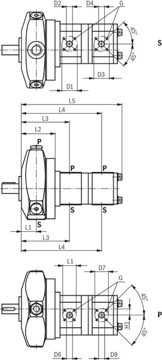
| L1 | mm | 38.5 | ||||||
| L2 | mm | 86.8 | ||||||
| L3 | mm | 125.4 | 127.5 | 131.3 | ||||
| L4 | mm | 208.4 | 212.5 | 215.8 | 217.5 | 218.7 | 220.8 | 233.5 |
| L5 | mm | 254.7 | 258.8 | 265.4 | 263.8 | 266.3 | 270.4 | 292.2 |
| Ø D1 | mm | 40 | ||||||
| mm | ± 0.15 | |||||||
| Ø D2 | mm | 15 | 20 | |||||
| Ø D3 | mm | 40 | ||||||
| mm | ± 0.15 | |||||||
| Ø D4 | mm | 15 | 20 | 15 | 20 | |||
| Ø D5 | mm | 35 | ||||||
| mm | ± 0.15 | |||||||
| Ø D6 | mm | 15 | ||||||
| Ø D7 | mm | 35 | ||||||
| mm | ± 0.15 | |||||||
| Ø D8 | mm | 15 | ||||||
| H1 | mm | 15.7 | ||||||
| G | M6 | |||||||
| mm | 13 | |||||||
Project planning information
Installation instructions
Fluid tank
- Adjust useful volume of the tank to the operating conditions.
- The admissible fluid temperature must not be exceeded; use coolers, if necessary.
Lines and ports
- Remove protection plugs from the pump.
- We recommend the use of seamless precision steel pipes according to DIN EN 10305-1 and removable pipe connections.
- Select the clear width of pipes according to the ports (suction speed 1 to 1.5 m/s).
- Inlet pressure, see technical data.
- Thoroughly clean pipelines and fittings prior to installing.
Proposal for piping layout
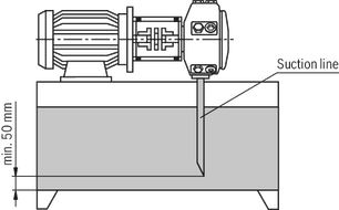
- Under no circumstances may drain and returning fluid be drawn directly into the suction port again, i.e., select the largest possible distance between suction line and return line.
- The return drain must always be below the oil level.
- Ensure suction-tight installation of the pipes.
Filter
Use a return flow or pressure filter, if possible.
(Suction filters only in connection with underpressure switch/clogging indicator).
Hydraulic fluid
- Please observe our specifications according to data sheet 90220.
- We recommend brand name hydraulic fluids.
- Do not mix hydraulic fluids of different types since this can result in decomposition and deterioration of the lubricity.
- The hydraulic fluid must be replaced at regular intervals according to the operating conditions. When doing this, the hydraulic fluid reservoir must also be cleaned of residues.
Drive
Electric motor + pump carrier + coupling + pump
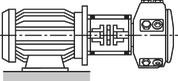
- No radial or axial forces permissible on the pump drive shaft!
- Motor and pump must be exactly aligned!
- Always use a coupling that is suitable for compensating for shaft offsets!
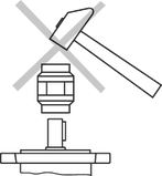
- When installing the coupling, avoid axial forces, i.e., when installing, do not hammer or press the coupling onto the shaft! Use the female thread on the drive shaft.
Installation positions
B3
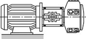
B5
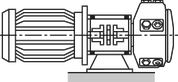
V1
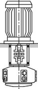
Project planning information
When using radial piston pumps, we recommend particularly observing the information specified below. Project planning, assembly and commissioning of the radial piston pumps require the employment of trained experts.
Technical data
All specified characteristic depend on production tolerances and are valid at certain boundary conditions. Please note that consequently, certain scatter ranges are possible and that with changed boundary conditions (e.g. viscosity), the characteristics may also change.
Characteristic curves for flow and consumed power
When designing the drive motor, please observe the maximum application parameters possible.
Noise
The values for sound pressure level shown under Diagrams/characteristic curves have been measured according to DIN 45635 part 26. That means only the sound emission of the pump is shown. Environmental influences (such as place of installation, piping, etc.) have been eliminated. The values are in each case only valid for one pump. For circulation at zero pressure, the pressure line must be preloaded by means of a check valve (cracking pressure p = 5 bar) due to noise development.
Notice
Due to the power unit construction and the influence at the final place of installation of the pump, the sound pressure level will usually be 5 to 10 dB(A) higher than the value of the pump itself.
Project planning information for multiple pumps
Project planning information for multiple pumps
| ||
| Pump type | Max. admissible | |
| Drive torque Tmax | Output torque Tmax | |
| PR4... | 160 Nm | 45 Nm |
| AZPF... | 45 Nm | 45 Nm |
| AZPFF... | 45 Nm | 45 Nm |
| Single pump 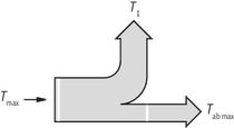 | 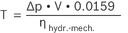 Example:    Tab2 = 45 Nm
T3 = 3.8 Nm ≤ Tab2 max
Tab1 = 45 Nm
T1,2 = T2 + T3
T1,2 = 18.8 Nm ≤ Tab1 max
Tmax = 160 Nm
T = T1 + T2 + T3
T = 63 Nm ≤ Tmax
|
| Combination pump 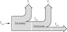 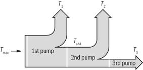 | |
| Calculation example: V = displacement in cm3 ηhydr.-mech. = hydraulic-mechanical efficiency T = torque in Nm Δp = pressure in bar
| The pump combination can be operated with the calculated key data. |
Commissioning
Commissioning instructions
Air bleeding
- All PR4 radial piston pumps are self-priming.
- Fill the housing with filtered oil via port S.
- During initial commissioning, set the pump to pressureless circulation. To do so, release the pressure hose and direct it into the reservoir.
- Before initial commissioning, the pump must be air-bled to protect it against damage.
- Switch to pressureless circulation, or direct the pressure line or pressure hose back into the reservoir.
- Briefly switch the pump on (inching mode).
- Should the pump not displace bubble-free oil after approx. 20 seconds, re-check the system. After the operating values have been reached, check the pipe connections for leakage. Check the operating temperature.
- Be aware of noise generation.
Commissioning
- Check whether the system is thoroughly and properly installed.
- Start the pump without load and let it displace fluid without pressure for a few seconds in order to ensure sufficient lubrication.
- In no case may the pump be operated without hydraulic fluid!
Note
- Adjustment, maintenance and repair of the pump may only be carried out by authorized, trained and instructed personnel!
- Use only original Rexroth spare parts!
- The pump may only be operated within the permissible data.
- The pump may only be operated when in perfect condition!
- When carrying out any work on the pump (e.g. installation and removal) the system must be switched off and depressurized!
- Unauthorized conversions and changes, affecting the safety and function are not permissible!
- Mount protective devices (e.g., coupling protection)!
- Do not remove any existing protective devices!
- The generally valid safety and accident prevention regulations must be strictly observed!
Downloads
 | Fixed displacement radial piston pump Data Sheet | RE11263 | 2013-05-01 | English | PDF | 504k Product Groups: Radial piston pumps Type PR4 |

Нет отзывов об этом товаре.