
Артикул: RX7807
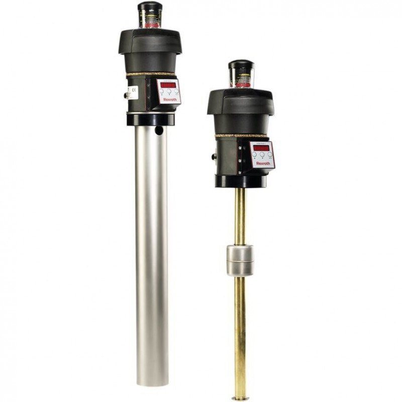
Float switch with breathering filter, level and temperature monitoring ABZMS-37
Доступно к заказу
Цена по запросу
И выбери подходящего.
Description
Product description
Float switches are switching devices operated by a float moved by fluid. These are used to control fluid levels in power unit tanks.
Three series are available:
- Float switches type …M consisting of a breathing filter, level monitoring (max./min.) and temperature measurement and display with two adjustable alarm outputs
- Float switches type …N consisting of a breathing filter, level monitoring (max./min.) and temperature measurement with one contact
- Float switches type …R consisting of a breathing filter, a resistance measuring chain for level, a resistance thermometer for temperature with analog output from 4 to 20 mA and an analog temperature display
Float switch type ...M
Tank venting function
Breather filter with filtration rating of 3 µm absolute.
The visual analog clogging indicator shows the increase in the degree of contamination of the filter element in percent.
Level switch function
Two reed contacts are provided in the sliding tubes (normally closed contact and normally open contact), which are switched by the permanent magnet installed in the float.
When the float reaches the switching points while the oil level is falling, the contacts are operated by magnetic force. The positions of the contacts are maintained until the float passes the switching points again when the oil level is rising.
The switching points are factory-set (for values, see "Oil volume indication").
As a standard, switching point L1 is installed as a normally closed contact, and switching point L2 as a normally open contact.
The switching points can be adjusted within the device (for instructions, see "Oil volume indication").
The switching function can be changed by rotating the contacts through 180°; the normally closed contact becomes a normally open contact and vice versa.
Temperature display
The current temperature is shown on a clearly visible LED display, which also signals status messages. The temperature is displayed in °C or °F.
Temperature signal function
Temperature is sensed by a PT 100.
The two temperature signals can be adjusted by means of the three keys provided on the control device.
The settings are protected against unauthorized access through programming guidance (see "Commissioning - operating and installation instructions").
Float switch type ...N
Tank venting function
Breather filter with filtration rating 3 µm absolute.
The visual analog clogging indicator shows the increase in the degree of contamination of the filter element in percent.
Level switch function
Two reed contacts are provided in the sliding tubes (normally closed contact and normally open contact), which are switched by the permanent magnet installed in the float.
When the float reaches the switching points when the oil level is falling, the contacts are operated by magnetic force. The positions of the contacts are maintained until the float passes the switching points again when the oil level is rising.
The switching points are factory-set (for values, see table on "Oil volume indication").
As a standard, switching point L1 is installed as a normally closed contact, and switching point L2 as a normally open contact.
The switching points can be adjusted within the device (for instructions, see "Oil volume indication").
The switching function can be changed by rotating the contacts through 180°; the normally closed contact becomes a normally open contact and vice versa.
Temperature signal function
Temperature is sensed by a PT 100.
A bimetal plate, which is influenced by temperature, switches when the firmly set response temperature is reached.
Float switch type ...R
Tank venting function
Breather filter with filtration rating 3 µm absolute.
The visual analog clogging indicator indicates the increase in the degree of contamination of the filter element in percent.
Level switch and temperature signal function
The sliding tube accommodates the resistance measuring chain with a resolution of 7.5 mm for continuous monitoring of the fill levels.
Permanent magnets installed in the float switch the contacts and activate a resistance.
The resistance thermometer (PT100) for temperature sensing is also integrated in the sliding tube.
A measuring transducer, which is integrated in the connected housing, converts the level- and temperature-related signal into a linear current change of 4 to 20 mA.
Temperature display
A clearly visible LED display indicates the current temperature.
The temperature is shown in °C or °F (how to change the indication is described at "Commissioning - operating and installation instructions").
Type code
Ordering code
| 01 | 02 | 03 | 04 | 05 | 06 | 07 | 08 | 09 | 10 | ||||||||
| ABZM | S | ‒ | 37 | ‒ | 1X | / | ‒ | 03 | ‒ | ‒ | ‒ | ‒ | K24 |
| Power unit accessories | ||
| 01 | Measuring devices | ABZM |
| 02 | Float switches | S |
| 03 | Version | 37 |
| 04 | Component series 10 ... 19 (10 ... 19: unchanged installation and connection dimensions) | 1X |
| Ordering length in mm | ||
| 05 | L = 370 mm | 0370 |
| L = 500 mm | 0500 | |
| L = 800 mm | 0800 | |
| L = 10 mm | 1000 | |
| L = 1.200 mm | 1200 | |
| Breathing filter | ||
| 06 | Filter rating 3 μm | 03 |
| Functions | ||
| 07 | Level: with 2 switching contacts (normally closed contact/normally open contact) | M |
| Level: with 2 switching contacts (normally closed contact/normally open contact) | N | |
| Level: with resistance measuring chain (analog output 4 to 20 mA) | R | |
| Temperature contact | ||
| 08 | Version M | |
| Without temperature contact | no code | |
| Version N | ||
| Switching contact normally closed contact at 60 °C | T60F | |
| Switching contact normally closed contact at 70 °C | T70F | |
| Switching contact normally closed contact at 80 °C | T80F | |
| Version R | ||
| With resistance thermometer | no code | |
| Option | ||
| 09 | With adapter flange | no code |
| Without adapter flange 1) | F | |
| Electrical connection 2) | ||
| 10 | Connector, 4-pole M12 x 1 | K24 |
| 1) | Design without adapter flange for fluid manager (see R.50230) |
| 2) | The mating connectors are not included in the scope of delivery and must be ordered separately, if required (see R.08006) |
| Order example: | |
| Float switch with flange connection, with breathing filter, with temperature display and control unit, with two pre-set switching contacts (level and temperature), ordering length 370 mm and electric connection K24 for round connector M12 x 1: | |
| ABZMS-37-1X/0370-03-M-K24 |
Technical data
Resistance
| Hydraulic fluids | ||||
| Mineral oils | Mineral oil | HLP | according to DIN 51524 | Resistant |
| Flame-resistant hydraulic fluids | Emulsions | HFA-E | according to DIN 24320 | Resistant |
| Water solutions | HFC | according to VDMA 24317 | ||
| Phosphoric acid esters | HFD-R | Not resistant | ||
| Organic esters | HFD-U | |||
| Fast bio-degradable hydraulic fluids | Triglycerides (rape seed oil) | HETG | according to VDMA 24568 | Resistant |
| Synthetic esters | HEES | |||
| Polyglycols | HEPG | |||
electrical
| Plug-in connection | 4-pole M12 x 1 (material: metal) |
Reed contacts of the float switches
with connection K24 for mating connector M12 x 1; 4-pole
| Switching voltage range | V DC | 10 … 30 |
| Maximum switching current | A | 0.5 |
| Maximum switching power | W | 10 |
Temperature display
| Temperature display range | °C | -20 … +120 | |
| Alarm temperature adjustment range | only with type …M | °C | 0 … 99 |
| Maximum programmable switching points | 2 | ||
| Housing design | PA, IP65 | ||
| Current consumption upon switch-on | more than 100 ms | mA | ≈ 140 |
| Current consumption during operation | mA | ≈30 … 50 | |
| Power supply | V DC | 24 ±10 | |
| Outlet | PNP | ||
| Resolution | °C | 1 | |
| Operation | 3 keys | ||
| Temperature sensor | Pt100 | ||
Resistance measuring chain and resistance thermometer
with connection K24 for mating connector M12 x 1; 4-pole
| Switching voltage range | V DC | 10 … 30 |
| Outlet | mA | 4 … 20 |
| Resolution resistance measuring chain | mm | 7.5 |
| Maximum load resistance | R = UB ‒ 7,5 V (0,02 A) | |
| Residual ripple | % | 1 |
| Temperature measuring range | °C | 0 … 100 |
Symbols/Circuit diagrams
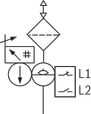
Type …M
With two switching contacts, two temperature contacts, temperature display and control unit
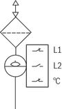
Type …N
With two switching contacts and one temperature contact
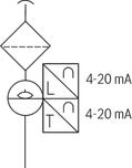
Type …R
With resistance measuring chain/resistance thermometer
Dimensions
Dimensions: Float switch type ...M
With breathering filter, with two adjustable switching contacts for level, with temperature indicator and two adjustable temperaturesignals in the control device, Plug-in connection M12 x 1, max. 30 VDC
Dimensions in mm
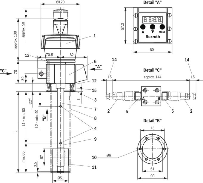
| 1 | Breathing filter |
| 2 | Mating connector for plug-in connections K24 (M12 x 1), see table "Mating connector" |
| 3 | Flat seal |
| 4 | Switching points |
| 5 | Connector K24; 4-pole M12 x 1 |
| 6 | Name plate |
| 7 | Float switch variant L up to 370 mm without protective tube |
| 8 | Float switch variant L 500 mm or longer with protective tube |
| 9 | Tube Ø 20 mm |
| 10 | Bore pattern 6 x 60° to DIN 24557 part 2 |
| 11 | Float with permanent magnet, radially magnetized, north pole inside (dimensions: Ø51 x 57; Material 1.4571) |
| 12 | Mounting screw M5 x 20 (adapter flange to tank) |
| 13 | Mounting screw M5 x 80 (float switch to adapter flange) |
| 14 | Space required to remove the mating connector |
| 15 | Adapter flange (not required when mounted on Fluid Manager ABZMF...) |
| Dimensions L, L1 and L2, see "Oil volume indication" | |
Pinout
| Switching function with plug-in connection M12 x 1 | |||
M12 plug-in connector A 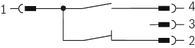 | Pin assignment | ||
| 1 = | max. 30 VDC | ||
| 4 = | level / L2 | ||
| 2 = | level / L1 | ||
M12 plug-in connector B  | Pin assignment | ||
| 1 = | max. 30 VDC | ||
| 4 = | temperature switching point 1 (freely adjustable from 0 to 100 °C) | ||
| L1 = | Normally closed contact at min. value, falling | 2 = | temperature switching point 2 (freely adjustable from 0 to 100 °C) |
| L2 = | Normally open contact as early warning, falling | 3 = | GND |
Dimensions: Float switch type ...N
With breathering filter, one thermal contact and two adjustable switching contacts for level, plug-in connection M12 x 1, max. 30 VDC
Dimensions in mm
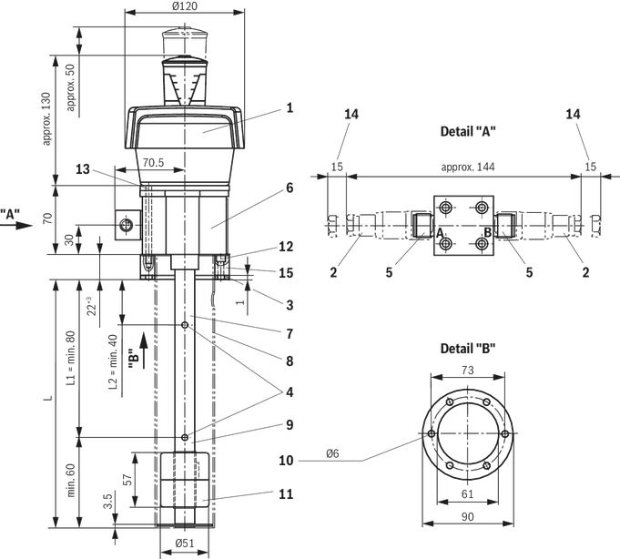
| 1 | Breathing filter |
| 2 | Mating connector for plug-in connections K24 (M12 x 1), see table "Mating connector" |
| 3 | Flat seal |
| 4 | Switching points |
| 5 | Connector K24; 4-pole M12 x 1 |
| 6 | Name plate |
| 7 | Float switch variant L up to 370 mm without protective tube |
| 8 | Float switch variant L 500 mm or longer with protective tube |
| 9 | Tube Ø 20 mm |
| 10 | Bore pattern 6 x 60° to DIN 24557 part 2 |
| 11 | Float with permanent magnet, radially magnetized, north pole inside (dimensions: Ø51 x 57; Material 1.4571) |
| 12 | Mounting screw M5 x 20 (adapter flange to tank) |
| 13 | Mounting screw M5 x 80 (float switch to adapter flange) |
| 14 | Space required to remove the mating connector |
| 15 | Adapter flange (not required when mounted on Fluid Manager ABZMF...) |
| Dimensions L, L1 and L2, see "Oil volume indication" | |
Pinout
| Switching function with plug-in connection M12 x 1 | ||
M12 plug-in connector A 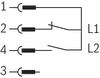 | Pin assignment | |
| 1 = | max. 30 VDC | |
| 4 = | level / L2 | |
| 2 = | level / L1 | |
M12 plug-in connector B  | Pin assignment | |
| 1 = | max. 30 VDC | |
| 2 = | Temperature contact | |
Dimensions: Float switch type ...R
With breathering filter, with resistance measuring chain (level), with temperature indicator and resistance thermometer (temperature) with two analog otuputs 4 to 20 mA, plug-in connection M12 x 1, max. 30 VDC
Dimensions in mm
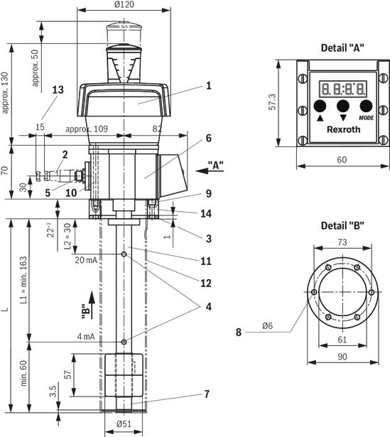
| 1 | Breathing filter |
| 2 | Mating connector for plug-in connections K24 (M12 x 1), see table "Mating connector" |
| 3 | Flat seal |
| 4 | Switching points |
| 5 | Connector K24; 4-pole M12 x 1 |
| 6 | Name plate |
| 7 | Resistance thermometer (PT100) |
| 8 | Bore pattern 6 x 60° to DIN 24557 part 2 |
| 9 | Mounting screw M5 x 20 (adapter flange to tank) |
| 10 | Mounting screw M5 x 80 (float switch to adapter flange) |
| 11 | Float switch variant L up to 370 mm without protective tube |
| 12 | Float switch variant L 500 mm or longer with protective tube |
| 13 | Space required to remove the mating connector |
| 14 | Adapter flange (not required when mounted on Fluid Manager ABZMF...) |
| Dimensions L, L1 and L2, see "Oil volume indication" | |
Oil volume specification for float switch
Types ...M and ...N with factory-set switching points
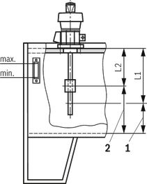
| 1 | Residual quantity with switching point L1 |
| 2 | Residual quantity with switching point L2 |
| Float switch Ordering length "L" | Switching points pre-set | Residual hydraulic fluid volume at switching point | |||
|
|
| AB 40-40, AB 40-43, AB 40-44 | |||
| L1 | L2 | NG | L1 | L2 | |
| mm | mm | mm | l | l | |
| 500 | 220 | 140 | 63 | 28 | 42 |
| 220 | 140 | 100 | 45 | 67 | |
| 220 | 140 | 160 | 74 | 100 | |
| 220 | 140 | 250 | 120 | 174 | |
| 220 | 140 | 400 | 190 | 277 | |
| 220 | 140 | 630 | 365 | 475 | |
| 220 | 140 | 800 | 460 | 600 | |
| 280 | 160 | 1000 | 490 | 740 | |
| 280 | 160 | 1250 | 780 | 1030 | |
| 280 | 160 | 1600 | 990 | 1310 | |
| 280 | 160 | 2000 | 1380 | 1730 | |
| 800 | 600 | 400 | - | - | - |
| 1000 | 700 | 500 | - | - | - |
| 1200 | 800 | 600 | - | - | - |
Attention!
Before commissioning, adjust the upper and lower switching contact according to the relevant operating conditions.
Adjustment of the switching height
- Interrupt the power supply
- Remove filter cover and take filter element out
- Loosen six mounting screws and remove filter reservoir
- Loosen four screws of the flange cover and remove cover with cover seal
- Carefully remove adapter plug from contact strip (Attention! Some cables of the adapter plug are firmly soldered to the control device).
- Carefully take out contact strip to the top
- Loosen the plastic screws at the contacts and re-position contacts with the help of the cm scale, which is provided at the rear of the contact strip. The height can be adjusted in 1 cm increments. Tighten the plastic screws for contact mounting hand-tight.
- During the assembly, take care that the adapter plug is plugged correctly onto the contact strip.The correct direction is shown by the red marking on the adapter plug and the contact strip.
As a standard, the contacts for switching point L1 are installed as normally closed contact, and for switching point L2 as normally open contact. Since these are bistable contacts, the contact function of the normally open contact and the normally closed contact can be changed by rotating the contacts around 180°.
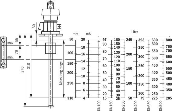
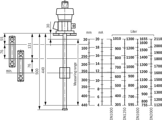
Type ...R
in tank according to AB 40-40, AB 40-43 and AB 40-44Tank size DN100 to 800
Dimensions in mm
Tank size DN1000 to 2000
Dimensions in mm
Installation opening of the tank cover
Dimensions in mm
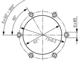
Standard breakthrough AB 03-39.73 similar to DIN 24557 part 2
Fastening screws:
6 HEXAGONSOCKET HEAD CAP SCREWS ISO4762-M5X18-8.8-A2P; Material no. R900202612
Adapter for float switch AB 31-04
If float switches according to R.50216 are installed as replacement for float switches according to AB 31-04, an adapter - consisting of item 1 to 3 - is necessary.
ADAPTER AB31-04/AB31-36 BG, material no. R901078947
Assembly sequence:
1. Assemble the adapter flange at the tank
2. Assemble the float switch at the adapter flange
Dimensions in mm

| 1 | Adapter flange |
| 2 | Flat seal |
| 3 | 4 hexagon socket head cap screw M8 x 16 |
Mounting
Installation information
- Vertical installation according to technical data (see “Technical data”)
- Avoid flows
- Do not expose the switch to heavy impacts and bends
- Avoid external magnetic fields. Thus, the function of the reed contacts may be impaired.
Electrical connections:
- Electrical connections may only be established by specialists
- Before works at electric parts, the voltage supply is to be interrupted
- Tighten the round connectors M12 x 1 and/or mating connectors after connection
- Only plug in the round connectors M12 x 1 and/or mating connectors in the de-energized condition
- Do not overload the contacts (see technical data)
- In case of inductive load provide a protection circuit!
Commissioning
Operating and installation instructions for float switch type ...M with control device
General operating notes
The temperature switching points can be changed or adjusted by means of three keys ( Δ )+( ∇ )+(MODE).
To this end you have to select the individual menu items by pressing key (MODE) and one of the keys ( Δ ) or ( ∇ ).
When you navigate through the menus, the relevant menu name is shown on the display.
You can change the values in the relevant menu item by pressing key ( Δ ) or ( ∇ ). When you press the key (MODE) alone, the active place in the display changes over (units to tens digit and vice versa). This possibility was provided to simplify the entry of parameters. The active digit is marked by a flashing dot.
If you scroll beyond the end of the menu (upwards or downwards), the display changes back to the normal operating mode.
If no key is pressed and/or no parameter changed for 15 seconds, the menu is exited automatically and the display changes over to the normal operating mode. To return to the menu, you have to press the two keys ( Δ ) + (MODE) again.
After the menu was exited, all new parameters are automatically and permanently saved. All parameters are written to an internal EEPROM and are retained even in the case of a power failure.
Adjustment of the switching points (only for display with switching outputs)
Each switching output are assigned TWO parameter menus in the menu. For the first switching output, these can be, for example, menus 100 and 101. 100 refers to the switching back point (RESET) of output 1, and 101 the switching-on point (SET) of output 1. Due to the separate input of both parameters, it is possible to set an almost optionally great switching hysteresis for the corresponding switching output. In addition, it is possible to change the switching function of the output from a normally open contact to a normally closed contact by exchanging the values of the switching-on point (SET) and the switching-off point (RESET).
Example 1:
For 100 (RESET) a value of 40 is set.
For 101 (SET) a value of 45 is set.
Result:
Output 1 closes at 45° when the temperature is rising, and only opens when the temperature has fallen to 40°.
Switching function: Normally open contact at rising temperature
Example 2:
For 100 (RESET) a value of 45 is set.
For 101 (SET) a value of 40 is set.
Result:
Output 1 opens at 45° when the temperature is rising and only closes again when the temperature has dropped to 40°.
Switching function: Normally closed contact while the temperature is rising.
Switching the device on
After connection of the supply voltage the device runs some self-tests. These are shown on the display.
| Display | Status displays |
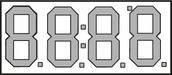 | First, all segments of the display are switched on for checking purposes. |
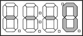 | The following indication means that all memory contents, e.g. for switching points or calibration of the 4 … 20 mA output, are OK. The last place on the display shows another value depending on the variant. |
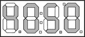 | Finally, the software version of the control device is displayed. |
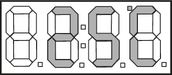 | The control device is now in the normal operating mode. The actual temperature is displayed. |
Status indicator lamps of the device
During normal operation, the status indicators light up in addition to the temperature indication.
| Display | Status displays |
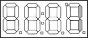 | The two LED segments on the right flash when the corresponding switching temperature of the relevant output has been reached (only for switching devices with switching outputs). |
 | During normal operation, the dot in the bottom right corner flashes. It serves as ready indicator and shows that the device functions properly. |
 | If you are in the adjustment or calibration menu, the point is permanently on until you exit the menu again. |
Faults
| Display | Cause | Remedy |
| No function | No operating voltage | Check operating voltage |
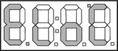 | Short-circuit in cable or PT100 | Replace contact strip |
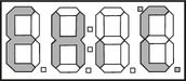 | PT 100 defective Cable connection is interrupted | Replace contact strip Connect cable connection |
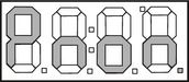 | General malfunction. In this case, all functions of the control device are inoperable. | Contact our Service: Tel. +49 93 52 18-11 64 |
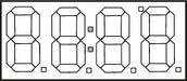 | The two central dots are flashing during normal operation when the memory contents may be damaged. | Check the settings. If required, contact our Service: Tel. +49 93 52 18-11 64 |
Changing the displayed unit
| Display | Operation |
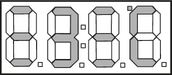 | Unlock keylock. Press (Δ) + (MODE) SIMULTANEOUSLY.In the first and third place, 3 horizontal dots are displayed, while the second place counts down from 9 to 0. |
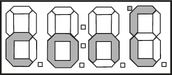 | Then, the display on the left appears. The keys can now be released. |
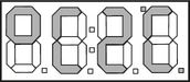 | On the current display you can change the temperature indication from degrees Celsius to degrees Fahrenheit by pressing the (∇) key. |
Adjustment of the switching points
| Display | Status displays |
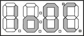 | To go to the adjustment menu for the switching-off point of the first output, press the (MODE) + (Δ) keys. After having released the (MODE) key you can change the values with the help of keys (Δ) + (∇). |
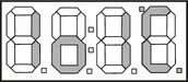 | To go to the adjustment menu for the switching-on point of the first output, press the (MODE) + (Δ) keys. After having released the (MODE) key you can change the values with the help of keys (Δ) + (∇). |
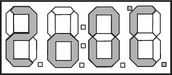 | To go to the adjustment menu for the switching-off point of the second output, press the (MODE) + ( Δ ) keys. After having released the (MODE) key you can change the values with the help of keys (Δ) + (∇). |
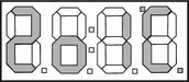 | To go to the adjustment menu for the switching-on point of the second output, press the (MODE) + (Δ) keys. After having released the (MODE) key you can change the values with the help of keys (Δ) + (∇). |
Information
Normative cross-reference
AB 03-39.73
Normdurchbruch, Einfülladapter für VW und DB-Norm
AB 24-02
Kabelsätze und Verteiler
R.50212
Float switches with two switching contacts and one thermal contact
R.50214
Float switches with two switching contacts and with one thermal contact, with resistance measuring chain/resistance thermometer
AB 40-40
Steel reservoirs, form AN, cover form C, drip tray to WHG
AB 40-43
Steel reservoirs, cover form C
AB 40-44
Steel reservoirs, with base frame
R.08006
Cable sockets for controlling electrically operated valves and sensors
DIN 24320
Fire resistant fluids; hydraulic fluids of category HFAE, properties, requirements
DIN 24557-2
Fluid power; breather filters; connecting dimensions
DIN 51524
Pressure fluids; hydraulic oils
ISO 4762
Hexagon socket head cap screws
VDMA 24317
Fluidtechnik; biologisch schnell abbaubare Druckflüssigkeiten; Technische Mindestanforderungen
VDMA 24568
Fluidtechnik; biologisch schnell abbaubare Druckflüssigkeiten; Technische Mindestanforderungen
94/9/EC (ATEX)
Directive 94/9EC of the European Parliament and the Council of 23 March 1994 on the approximation of the laws of the Member States concerning equipment and protective systems intended for use in potentially explosive atmospheres
Accessories
Mating connectors
| For detailed information see data sheet 08006 | |||
| Mating connector for connector K24 | Mating connector for connector K24 with potted-in PVC cable, 3 m long | ||
| Denomination | Material number | Denomination | Material number |
| LEITUNGSDOSE 4P Z24 SPEZ | R900031155 | LEITUNGSDOSE 4P Z24M12X1+3MSPEZ | R900064381 |
Mating connectors for sensors and valves with connector “K24”, “K35” and “K72”, M12 x 1
4P Z24
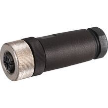
Mating connectors for sensors and valves with connector “K24”, “K35” and “K72”, M12 x 1
4P Z24
- For sensors and valves with connector “K24”, “K35” and “K72”
- Mating connectors M12, 4-pole, line cross-section 0.75 mm2
Mating connectors for sensors and valves with connector “K24”, “K35” and “K72”, M12 x 1, with assembled connection line
4P Z24 +
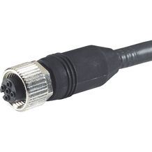
Mating connectors for sensors and valves with connector “K24”, “K35” and “K72”, M12 x 1, with assembled connection line
4P Z24 +
- For sensors and valves with connector “K24”, “K35” and “K72”
- Mating connectors M12, 4-pole, line cross-section 0.75 mm2
Safety Instructions
Use in potentially explosive atmospheres according to Directive 94/9/EC (ATEX)
Float switches ABZMS-37 are not suitable for use in potentially explosive atmospheres.
Ordering codes
Currently eShop is not available. Please try again later.Downloads
 | Float switch with breather filter, level and temperature monitor Data Sheet | RE50216 | 2007-12-01 | English | PDF | 417k Product Groups: Power units Type ABZMS-37 |

Нет отзывов об этом товаре.