
Доступно к заказу
Цена по запросу
И выбери подходящего.
Description
- Analog output signals (Sinus 1Vss)
- Digital output signals (TTL 1µ, 5µ, 10µ)
Technical data
Analog output signals, sinusoidal signals 1 Vpp
(option I1)
Incremental signals
The sinusoidal incremental signals A and B are phase offset by 90° to each other and have a typical signal amplitude of 1 Vpp.
Signal amplitude: A, B = 1 Vpp (±0.1 V)
The illustrated output signal sequence (B phase-lagged to A) applies to scanner motions in the positive counting direction (see graph).
Reference mark signal
The differential reference mark signal RI has an amplitude of about -0.7 V when inactive (low). In an active state (high) the amplitude is +0.7 V.
Representation:
A, B sinusoidal incremental signals
RI reference mark signal
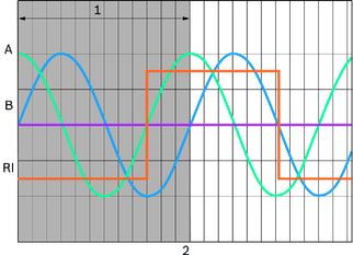
1 Signal period (40 µm)
2 Travel
Interface circuitry for analog output signals
The stated amplitude values apply for operation with a terminating resistor Z0 = 120 Ω.
RA = 27.40 Ω
RRI= 0 Ω
Z0 = 120 Ω
Ucom = 1.65 V
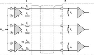
1 scanner
2 signal processing electronics
Digital output signals, square-wave output signals TTL through integrated interpolation unit
(options I2, I3, I4)
Incremental signals
The digital incremental signals A and B comply with the EIA/TIA-422-A standard. They are phase offset by 90° and have the following signal levels:
Uhigh > 2 V
Ulow < -2 V
The switching response times are ≤ 100 ns at a capacitive load of ≤ 1000 pF.
Reference mark signal
The differential reference mark signal RI has the same electrical characteristics as the incremental signals.
The stated amplitude values apply for operation with a terminating resistor Z0 = 120 Ω. (See interface circuitry)
The graph shows: A, B and full differential RI for motion in the positive counting direction.
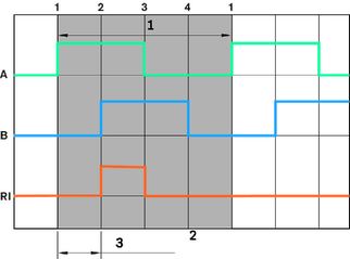
1 signal period
2 Travel
3 Edge spacing
Resolution
Measuring systems with digital output signals are available with the resolutions 1 µm, 5 µm, and 10 µm.
| Option | Resolution (edge spacing) | Signal period | Max. scanner speed |
|
| (μm) | (μm) | (m/s) |
| I2 | 1 | 4 | 2,0 |
| I3 | 5 | 20 | 5.0 |
| I4 | 10 | 40 | 5,0 |
| Power supply | 4.75 V to ... 12.6 V (at connector) Overvoltage protection: max. 18 V DC |
| Current consumption | 1 Vpp/5V: 300 mA; 1 VSS/12V: 170 mA; TTL/5V: 350 mA; TTL/12V: 190 mA; |
Downloads
 | Integrated Measuring System IMS for Ball and Roller Rail systems / Instructions for electrical interfaces / only PDF Manual | R320103166_EN | 2017-10-01 | English | PDF | 2.4MB Product Groups: Integrated measuring systems |
| Integrated Measuring System IMS for Ball and Roller Rail Systems Manual | R320103262_EN | 2020-07-01 | English | PDF | 1.8MB Product Groups: Integrated measuring systems |
| Catalog Integrated Measuring System IMS for Ball and Roller Rail Systems Catalog | R999000487 | 2020-06-01 | English | PDF | 2.7MB Product Groups: Ball Rail Systems, Roller Rail Systems, Integrated measuring systems Catalog Integrated Measuring System IMS for Ball and Roller Rail Systems |

Нет отзывов об этом товаре.