
Затрудняетесь с выбором?
Оставьте ваш телефон, и наш специалист перезвонит вам

Артикул: RX8289

Все товары Bosch Rexroth

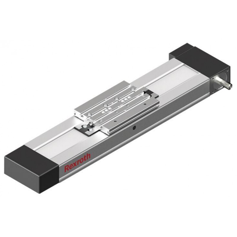
Compact Modules with toothed belt drive CKR-110-NN-1

Доступно к заказу

Цена по запросу

Получи КП от 5 лучших поставщиков
С указанием цены, наличия, сроков поставки и скидок.
И выбери подходящего.

Description

    Product description

    Structure and attachments

    Motor attachment – direct attachment with i = 1

    The motor is attached directly to the compact module’s drive end enclosure via a motor mount.

    Motor attachment – with gear

    The planetary gearbox is attached by a mount. The mount serves to fasten the gearbox to the CRK and as a closed housing. Due to the connection without coupling, the drive torque is transferred to the drive shaft of the Compact Module with minimal torsional deflection. Available gear ratios: i = 3 (for CKR-145 and CKR-200), i = 5, i = 10
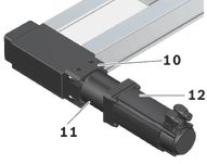
    Structural design

    1 Drive end enclosure

    2 Frame

    3 Belt drive

    4 Carriage

    5 Non-drive end enclosure

    Additional components

    6 Magnetic sensor

    7 Mounting duct

    8 Socket/plug

    9 Connection plate

    10 Flanged type

    11 Planetary gearbox

    12 Motor

    Attachments

    • Planetary gearbox with various gear ratios
    • Maintenance-free servo motors with selectable brake and attached feedback
    • Switches (magnetic sensors), switch activation without additional switch flag
    • Socket and plug
    • Mounting duct made of aluminum for sensors

    Design/options for guideway (frame), carriages, connection plates, see section “Dimensions”

    1)Guideway (frame)
    2)Carriages
    3)Connection plates

    Lubrication versions

    Lube version LSS, LPG

    • Grease lubrication with manual grease gun via frame, carriage or via connection plate
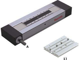
    1)Connection plates

    A Drive side

    Lube version LCF, LCO

    • 2 lube connections
    • Prepared for connection to central lubrication systems
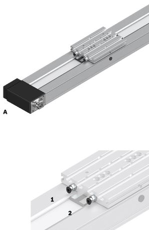
    A Drive side

    1 Lube connection, Runner Block left

    2 Lube connection, Runner Block right

    Notes:

    LSS:

    • Initial lubrication by Bosch Rexroth
    • Relubrication using manual grease gun

    LPG:

    • Ball Rail System and Ball Screw Assembly only with corrosion prevention
    • Relubrication using manual grease gun
    • Basic lubrication required

    LCF:

    • Prepared for connection to central lubrication systems for liquid grease (NLGI grade 00 in accordance with DIN 51818)
    • • Lubrication with liquid grease only via single-line piston distributor system
    • Basic lubrication required

    LCO:

    • Prepared for connection to central lubrication systems for oil
    • Oil lubrication only via single-line piston distributor system
    • Runner Block and Ball Screw Assembly nut with integrated non-return valves
    • Basic lubrication required

    Technical data

    Suitable loads

    Regarding the desired service life, loads for Fmgw, Fmbsshould not exceed around 20 % of the dynamic characteristic values (Cgw, Cbs).

    See Chapter "Project planning notes", document "Calculation".

    Do not exceed the technical data for the Linear Motion System.

    Note on dynamic load capacities and moments (see the table)

    Determination of the dynamic load ratings and moments is based on a total travel of 100,000 m.

    Often only 50,000 m are actually stipulated. For comparison: Multiply values C, Mt and ML from the table by 1.26.

    1)Applicable to CKK-110, -145, -200 with Resist cover

    Note: Observe the document "Calculation" in the section "Project planning notes".

    Load capacities and moments

    Size

    CKR-110

    Lca

    without connection plate 1)

    mm

    170215

    With connection plate 2)

    mm

    110155

    Cgw

    N

    1972032035

    ly

    cm⁴

    32.7

    lz

    cm⁴

    282.9

    Mt

    Nm

    6511057

    ML

    Nm

    1361361

    Mx max

    Nm

    198396

    My max

    Nm

    32510

    Mz max

    Nm

    32240

    Fy max

    N

    34805650

    Fz1 max

    N

    600012000

    Fz2 max

    N

    600012000

    Z1

    without connection plate

    mm

    28.7

    With connection plate

    mm

    44.7
    1)In the carriage design “without connection plate” the carriage length Lca corresponds to the length of the clamping surface.
    2)The connection plate is mounted on the carriage design “without connection plate.”
    For the design with connection plate, the carriage length Lca corresponds to the length of the connection plate.

    Note: Observe the document "Calculation" in the section "Project planning notes".

    General technical data

    Size

    CKR-110

    Lca

    without connection plate 1)

    mm

    170215

    With connection plate 2)

    mm

    110155

    Lad

    without connection plate

    mm

    25

    With connection plate

    mm

    85

    smin 3)

    mm

    50

    Lmax

    mm

    5500

    mca

    without connection plate

    kg

    0.520.87

    With connection plate

    kg

    0.91.45
    1)In the carriage design “without connection plate” the carriage length Lca corresponds to the length of the clamping surface.
    2)The connection plate is mounted on the carriage design “without connection plate.”
    For the design with connection plate, the carriage length Lca corresponds to the length of the connection plate.
    3)Minimum required travel distance to ensure a reliable lubrication distribution.

    Length calculation

    For length calculation values, see the "General Technical Data" table.

    Modulus of elasticity E of the Linear Motion System

    Effective stroke

    Stroke: Maximum distance from carriage center to the outer-most switch activation points.

    Excess travel: Excess travel must be greater than braking distance. The acceleration travel can be adopted as the guideline value for the braking distance.

    Mass of the Linear Motion System

    Weight calculation:
    - without motor
    - without switch mounting
    - without motor attachment

    Note: Observe the document "Calculation" in the section "Project planning notes".

    Drive data

    Size

    Gearbox

    i

    Mp

    u

    vmax

    Lca

    mca

    kg fix

    kg var

    kJ fix

    kJ var

    kJ m

    MRs

    d3

    Bt

    Fbp1)

    Ft zul2)

    amax

    without connection plate

    With connection plate

    without connection plate

    With connection plate

    without connection plate

    With connection plate

    Nm

    mm/U

    m/s

    mm

    mm

    kg

    kg

    kg

    kg/mm

    kgmm2

    kgmm2

    kgmm

    mm2

    Nm

    mm

    N

    N

    m/s2

    CKR-110

    -

    1

    13,50

    120

    5,0

    170

    60

    0,52

    0,90

    1,27

    0,00739

    266,45

    405,08

    0,1364

    364,81

    1,04

    38,2

    50 AT5

    705

    4200

    50

    PG050

    5

    2,72

    24

    4,4

    215

    155

    0,87

    1,45

    391,07

    602,66

    1,42

    10

    1,26

    12

    2,2

    1)Maximum power that can be transmitted through the engaging teeth that are in the belt pulley.
    2)The maximum permitted tensile load on the belt cross section (belt elasticity limit) is given here for easier comparability. This value represents the load limit in terms of plastic deformation and may not be used to calculate the maximum permissible drive torque.

    Mass moment of inertia of the linear system

    Determination of translative mass moment of inertia of the external load

    Note: Observe the document "Calculation" in the section "Project planning notes".

    Getriebedaten

    Size

    Gearbox

    Mge1)

    MRge

    nge

    Motor

    Jge

    mge

    Type

    i

    Nm

    Nm

    rpm

    Type

    kgm2

    kg

    CKR-110

    PG050

    5

    14

    0,09

    10000

    MS2N03-B

    0,0000030

    0,9

    MS2N03-D

    0,0000050

    MS2N04

    0,0000130

    1,4

    MSM031-C

    10

    13

    0,08

    MS2N03-B

    0,0000020

    0,9

    MS2N03-D

    0,0000040

    MS2N04

    0,0000130

    1,4

    MSM031-C

    1)The limit values of the Linear Motion System must not be exceeded, see “Calculation” document in the "Project planning instructions" chapter.

    Normal operating conditions

    Size

    CKR-110

    Permissible ambient temperature with Rexroth servo motor 1)

    ​0 °C ... +40 °C

    Permissible ambient temperature for mechanical system 2)

    -10 °C ... +60 °C

    smin 3)

    mm

    50
    1)Performance losses from 40°C
    2)No passing below the dew point
    3)Minimum required travel distance to ensure a reliable lubrication distribution.

    Note: Application of dirt is not permitted!

    Legend

    Symbol

    Description

    Unit

    amax

    Maximum acceleration travel

    m/s2

    Cgw

    Dynamic load capacity, linear guide

    N

    d3

    Diameter, belt pulley

    mm

    Fbp

    Maximum belt drive transmission force

    N

    Fmbs

    Dynamic equivalent load on bearing of the Ball Screw Assembly

    N

    Fmgw

    Dynamic equivalent load on bearing of the guideway

    N

    Ft zul

    Belt elasticity limit

    N

    Fy max

    Maximum dynamic load in y-direction

    N

    Fz1 max

    Maximum dynamic load in z-direction

    N

    Fz2 max

    Maximum dynamic load in z-direction

    N

    i

    Transmission

    -

    ly

    Y-axis planar moment of inertia

    cm4

    lz

    Z-axis planar moment of inertia

    cm4

    Js

    Mass moment of inertia of the linear system

    kgm2

    Jge

    Mass moment of inertia of the gear on the motor journal

    kgm2

    Jt

    Translatory mass moment of inertia of external load based on the Linear Motion System screw journal

    kgm2

    kg fix

    Constant for fixed portion of the mass

    kg

    kg var

    Constant for variable-length portion of the mass

    kg/mm

    kJ fix

    Constant for fixed-length portion of mass moment of inertia

    kgmm2

    kJ m

    Constant for mass-specific portion of mass moment of inertia

    mm2

    kJ var

    Constant for variable-length portion of mass moment of inertia

    kgmm

    L

    Length of linear motion system

    mm

    Lad

    Additional length

    mm

    Lca

    Carriage length

    mm

    Lmax

    Maximum length

    mm

    mca

    Moved mass of system of carriage

    kg

    mex

    Moved external mass

    kg

    mge

    Mass of the gear

    kg

    Mge

    Maximum permissible acceleration torque of the gear (on the output drive)

    Nm

    ML

    Dynamic longitudinal moment load capacity

    Nm

    Mp

    Max. permissible drive torque (at drive journal)

    Nm

    MRge

    Friction moment of belt side drive at motor journal

    Nm

    MRs

    Frictional torque of system

    Nm

    ms

    Mass of the Linear Motion System (without attachments)

    kg

    Mt

    Dynamic torsional moment load capacity

    Nm

    Mx max

    Maximum admissible torsional moment around the x-axis

    Nm

    My max

    Maximum admissible torsional moment around the y-axis

    Nm

    Mz max

    Maximum admissible torsional moment around the z-axis

    Nm

    nge

    Maximum permissible speed of the gear

    rpm

    PG

    Planetary gearbox

    -

    se

    Excess travel (excess travel se should be greater than braking distance. The acceleration travel can be used as a guideline for braking distance.)

    mm

    seff

    Effective stroke

    mm

    smax

    Maximum travel range

    mm

    smin

    Minimum travel

    mm

    u

    Lead constant

    mm/U

    vmax

    Maximum permissible speed

    m/s

    Z1

    Application point of the effective force

    mm

    Dimensions

    Straightness and flatness tolerance in accordance with DIN EN 12020-2.

    Notes: All dimensions are given in mm. Drawings not schematically to scale.

    Exact contours and dimensions can be found in the CAD model.

    For dimensional drawings for motor attachment, see Chapter "Motor attachment".

    For the length calculation of the Linear Motion System see Chapters “Technical data” and “Project planning notes”, document “Calculation”.

    Frame dimension drawings

    1)Lubrication bore on both sides (grease lubrication). For more information, see section “Maintenance”
    2)deep
    3)Version

    TT

    Carriage

    Dimensions

    Size

    CKR-110

    b

    P9

    mm

    5

    ⌀d

    h7

    mm

    14

    ⌀D

    H7

    mm

    42

    ⌀D1

    H7

    mm

    19

    h

    mm

    3

    H3

    mm

    24.5

    K1

    M5

    K2

    mm

    10

    K3

    mm

    35

    K4

    mm

    45

    K5

    mm

    25

    Toleranz für K5

    mm

    ± 0.1

    K6

    mm

    33

    K7

    M4 (ISO 4762)

    L1

    mm

    31.5

    L2

    mm

    66

    L3

    mm

    60.5

    L4

    mm

    25

    L5

    mm

    2

    L6

    mm

    2

    L7

    mm

    22

    L8

    mm

    8

    Tolerance for L8

    mm

    ± 0.2

    L9

    mm

    20

    L10

    mm

    17.5
    1)For connection plate, see section “Accessories”

    A

    For switch mounting arrangements

    B

    For mounting with clamping fixtures

    Dimensions

    Size

    CKR-110

    A

    mm

    110

    H

    mm

    50

    H1

    mm

    66

    H2

    mm

    49

    N1

    mm

    9.5

    Option 01 / standard

    View from below (ground area)
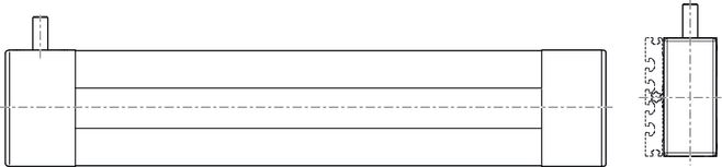
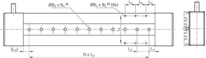
    Option 03 / with central holes

    View from below (ground area)
    1)deep

    Dimensions, option 03

    Size

    CKR-110

    B1

    M5

    B2

    mm

    9

    ⌀B3

    H7

    mm

    9

    B4

    mm

    2.1

    L1

    mm

    20

    L2

    mm

    40

    Tolerance for L2

    mm

    ± 0.01

    L3

    min

    mm

    10

    L4

    mm

    30

    L5

    mm

    35

    L6

    mm

    92

    Option 04 / with central holes and long hole

    View from below (ground area)
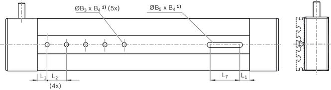
    1)deep

    Dimensions, option 04

    Size

    CKR-110

    ⌀B3

    H7

    mm

    9

    B4

    mm

    2.1

    B5

    H8

    mm

    9

    L1

    mm

    20

    L2

    mm

    40

    Tolerance for L2

    mm

    ± 0.01

    L7

    mm

    60

    Carriage dimension drawings

    Carriage without connection plate

    1)Fig. 1
    2)Fig. 2
    3)Fig. 3
    4)Fig. 4
    5)deep

    X

    Drive side

    Y

    Lubrication option for grease; closed with set screw.
    For further information on lubrication see chapter "Maintenance", CKR lubrication.

    Dimensions

    Size

    CKR-110

    Picture

    12

    Lca

    mm

    170215

    A

    mm

    34

    B

    mm

    50135

    C

    mm

    -85

    D

    mm

    -35

    E

    M5

    ⌀F

    H7

    mm

    6

    G

    mm

    46

    T1

    mm

    10

    T2

    mm

    6.5

    Carriages with connection plate

    Dimension diagrams, see section “Accessories,” connection plates

    Legend

    Symbol

    Description

    Unit

    L

    Length of linear motion system

    mm

    Lad

    Additional length

    mm

    Lca

    Carriage length

    mm

    LW

    Center-to-center distance between carriages

    mm

    se

    Excess travel (excess travel se should be greater than braking distance. The acceleration travel can be used as a guideline for braking distance.)

    mm

    seff

    Effective stroke

    mm

    smax

    Maximum travel range

    mm

    Project planning information

    Mounting

    Caution! Do not secure or support the Compact Module at the end enclosures! The frame is the load-bearing part!

    Mounting with clamping fixtures
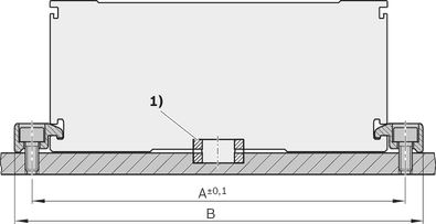
    1)For Compact Modules with centering holes in the ground area (selection via the guideway option): Use centering rings to better align to other Linear Motion Systems and connection elements.

    Size

    A

    B

    mm

    mm

    070

    82

    95

    090

    102

    112

    110

    126

    140

    145

    161

    175

    200

    222

    240

    Mounting by means of special modification in the base surface of the frame is possible

    Guideway option 03 already includes threaded holes in the ground area of the frame (see dimension drawings).

    Special modification in the base surface of the frame

    (not available from factory)

    1)Pin hole or thread max. ØB
    2)Distance from frame ends at least 30 mm
    3)Max. C

    Size

    A

    B

    C

    mm

    mm

    mm

    070

    59

    3

    7,5

    090

    76

    4

    7,5

    110

    92

    5

    9,0

    145

    124

    6

    13,0

    200

    119

    8

    12,0

    Magnetic sensor with free cable end

    1 Socket and plug

    2 Sensor

    3 Mounting duct

    Alternatively, the sensor can also be attached by switch mounting plate and cable holder.

    See the magnetic sensor with plug.

    1)Set screw for retention
    2)Active surface

    Additional component/actuation

    A mounting duct is needed to fasten the sensors and cable guides. This is suspended at the side in a slot at the Compact Module and secured with set screws (4).

    The set screws are included.

    The sensors are pushed into the upper T-slot (CKK/CKR-090,-110 and CKK-145) or into the lower T-slot (CKR-145, CKK/CKR-200) of the mounting duct and secured with set screws.

    Switch activation is done by magnets in the carriage.

    Socket - plug

    Notes:

    Socket and plug are not wired.

    This allows optimal assignment of switching positions during start-up.

    One plug is included.

    The plug can be installed in three directions.

    For further information, see the "Socket - plug” view.

    Magnetic sensor with plug

    1 Sensor

    2 Switch mounting plate including set screws (loose) and square nut 2a

    3 Cable holder including set screw (loose)

    Attachment/Actuation

    A switch mounting plate (2) is required to attach the sensors. This is suspended in the upper slot on the Compact Module and secured with set screws (4).

    The sensors are pushed into the respective slot on the switch mounting plate and secured with one set screw.

    The square nut with set screw (2a) serves as a fixed stop for the sensor (switching position when changing sensors). Parts are included in the scope of delivery of the sensor mounting kit.

    Switch activation is done by magnets in the carriage.

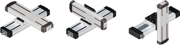
    Compact Modules fit together perfectly – fast and flexible

    Minimal mounting times, maximum efficiency:

    Standardized interfaces significantly reduce the effort during mounting.

    The mechanical systems have positive-locking interfaces throughout.

    They can be quickly and accurately connected together without time-consuming alignment.

    The result:

    Users can respond flexibly to handling the different applications and tasks.

    For more information about connection technology, see Connection technology for Linear Motion Systems and linear axes.

    Connection technology for Linear Motion Systems
    Commissioning

    Parameterization (start-up)

    The nameplate contains reference information on the production of the linear motion system as well as technical start-up parameters.

    Legend

    Position

    Symbol

    Description

    Unit

    1

    CNR

    Customer's part number

    -

    2

    TYP

    Short product name

    -

    3

    110

    Frame size

    -

    4

    CS

    Customer information

    -

    5

    MNR

    Part number

    -

    6

    FD

    Date of production

    -

    7

    7210

    Manufacturing location

    -

    8

    smax

    Maximum travel range

    mm

    9

    u

    Lead constant without motor attachment

    mm/U

    10

    vmax

    Maximum speed

    m/s

    11

    amax

    Maximum acceleration travel

    m/s2

    12

    M1max

    Maximum drive torque on the motor journal

    Nm

    13

    d

    Direction of motor rotation to move in positive (+) direction
    CW = clockwise
    CCW = counterclockwise

    -

    14

    i

    Transmission ratio

    -

    15

    -

    QR code

    -

    Maintenance

    Accessories

    Combination examples

    1) End of range (‒)
    2) Reference
    3) End of range (+)
    4) Sensors with plug
    5) Sensors with free cable end
    6) Plug
    7) Sensor extensions
    8) Performance specification: suitable for flexing installation, torsion-resistant, weld spark-resistant
    9) Plug
    10) Adapter
    1) End of range (‒)
    2) Reference
    3) End of range (+)
    4) Screw plug
    5) Sensors with plug
    6) Sensors with free cable end
    7) Sensors with plug
    8) Plug
    9) Passive distributor
    10) Holding plate
    11) Passive distributor
    12) Extensions for passive distributors
    13) Performance specification: suitable for flexing installation, torsion-resistant, weld spark-resistant
    14) Higher-level control system

    Clamping fixtures for Compact Modules

    Clamping fixtures for Compact Modules

      Sliding blocks and springs for Compact Modules

      Sliding blocks and springs for Compact Modules

        Strips for Compact Modules

        Strips for Compact Modules

          Centering rings for Compact Modules
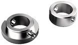
          Centering rings for Compact Modules

            Covers for Compact Modules

            Covers for Compact Modules

              Connection plates for CKR 090 … 200, R0375...16
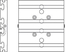
              Connection plates for CKR 090 … 200, R0375...16

                Connection plates for CKR 090 … 200, R0375...11
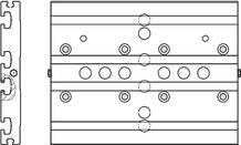
                Connection plates for CKR 090 … 200, R0375...11

                  Connecting shafts for CKR 090 … 200
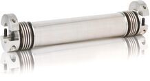
                  Connecting shafts for CKR 090 … 200

                    Magnetic sensor with free line end

                    Magnetic sensor with free line end

                      Magnetic sensor with M8x1 plug

                      Magnetic sensor with M8x1 plug

                        Proximity sensor with free line end

                        Proximity sensor with free line end

                          Proximity sensor with M8x1 plug

                          Proximity sensor with M8x1 plug

                            Mechanical switch

                            Mechanical switch

                              Mechanical switch with M8x1 plug

                              Mechanical switch with M8x1 plug

                                Extension pieces - assembled on one side

                                Extension pieces - assembled on one side

                                  Extension pieces - assembled on two sides

                                  Extension pieces - assembled on two sides

                                    Plug-in connector

                                    Plug-in connector

                                      Adapter

                                      Adapter

                                        Passive distributors

                                        Passive distributors

                                          Holding clip

                                          Holding clip

                                            Plug screw

                                            Plug screw

                                              Extension pieces

                                              Extension pieces

                                                Socket and plug

                                                R037540000

                                                Socket and plug

                                                R037540000

                                                  Socket and plug

                                                  R117500153

                                                  Socket and plug

                                                  R117500153

                                                    Mounting duct

                                                    Mounting duct

                                                      Switch mounting plate

                                                      Switch mounting plate

                                                        Cable holder

                                                        Cable holder

                                                          Nozzle pipe

                                                          R3455 031 06

                                                          Nozzle pipe

                                                          R3455 031 06

                                                          • For manual grease guns
                                                          • For the lubrication of funnel-type and ball-type lube nipples

                                                          Frequency meter

                                                          Frequency meter

                                                            Delivery notes

                                                            Form of delivery

                                                            Compact Modules with Ball Rail System and belt drive are delivered completely assembled.

                                                            Motor attachment

                                                            If a combination of motor and motor attachment has been selected, then the components are attached as shown in the figure, which also shows the location of the motor connector.

                                                            When ordering motor attachments without motor, not all parts can be mounted. Assembly must then be completed by the customer. All necessary instructions and parameters for professional assembly are included.

                                                            Direct attachment (MA10, MA11)

                                                            1)Linear motion system
                                                            2)Motor connector
                                                            3)Motor
                                                            4)Direct attachment (flange)

                                                            Planetary gearboxes (MG10, MG11, MG01-MG04)
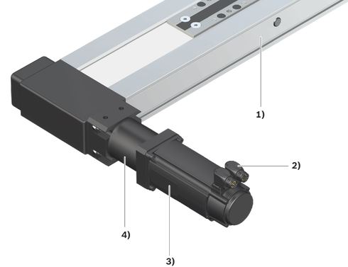
                                                            1)Linear motion system
                                                            2)Motor connector
                                                            3)Motor
                                                            4)Gearbox

                                                            Available options

                                                            Cable duct, mounting duct, switch, switching angle and socket with plugs are included as loose parts.

                                                            Lubrication

                                                            Compact Modules are delivered with initial greasing, depending on the lubricant used.

                                                            For more information on lubricants, see Chapter "Lubrication".

                                                            Documentation

                                                            Each Compact Module is supplied with the accompanying documentation.

                                                            Safety Instructions

                                                            Required and supplementary documentation

                                                            For further instructions and information, please refer to the documentation for this product.

                                                            You can find PDF files of these documents on the Internet at www.boschrexroth.com/mediadirectory.

                                                            We would also be happy to send you the documents that you want.

                                                            If you are unsure about using this product, please contact Bosch Rexroth.

                                                            Motor attachment

                                                            Version

                                                            X: Drive end enclosure with additional drive shaft
                                                            In the versions MA10, MA11, MG10 and MG11, a second drive shaft end can be made available by removing the screws and cover.

                                                            Motor attachment option 00 (adapter flange for customer-side gear attachment)

                                                            1)Cut A-A

                                                            Abmessungen

                                                            Size

                                                            Version

                                                            Motor code

                                                            ▢ E

                                                            Lf

                                                            Lge

                                                            Lm

                                                            ▢ A

                                                            A1

                                                            B

                                                            ⌀E

                                                            G

                                                            H

                                                            Tolerance for H

                                                            ⌀D

                                                            ⌀K

                                                            ⌀M

                                                            H7

                                                            H7

                                                            mm

                                                            mm

                                                            mm

                                                            mm

                                                            mm

                                                            mm

                                                            mm

                                                            mm

                                                            mm

                                                            mm

                                                            mm

                                                            mm

                                                            mm

                                                            mm

                                                            CKR-110

                                                            MA10, MA11

                                                            MS2N05-D0BRN

                                                            55

                                                            46,0

                                                            -

                                                            see Linear Motion Systems – motors and controllers

                                                            57

                                                            55

                                                            44

                                                            -

                                                            7

                                                            +0,4

                                                            19

                                                            35

                                                            4,5

                                                            MG10, MG11

                                                            MS2N03-B0BYN

                                                            30,5

                                                            68

                                                            MS2N03-D0BYN

                                                            MS2N04-B0BTN

                                                            80

                                                            75

                                                            MS2N04-C0BTN

                                                            MSM031C-0300

                                                            70

                                                            Adapter flange

                                                            Measurement and test reports

                                                            Downloads

                                                            Declaration of Incorporation for single axis Linear Motion Systems
                                                            Certificate | R320103141 | 2020-06-01 | All languages | PDF | 409k

                                                            Product Groups: Linear axes and electromechanical cylinders
                                                            Safety Instructions for Linear Motion Systems
                                                            Manual | R320103152_en | 2015-01-01 | English | PDF | 593k

                                                            Product Groups: Linear axes and electromechanical cylinders
                                                            Compact Modules CKK, CKR
                                                            Catalog | R999000499 | 2022-02-01 | English | PDF | 24.8MB

                                                            Product Groups: Compact Modules
                                                            Compact Modules CKK, CKR

                                                            Мы предлагаем следующие способы доставки товара:

                                                            Самовывоз из пункта выдачи

                                                            Самостоятельное получение заказа в пункте выдачи. Дата и время получения заранее согласуется с менеджером магазина.
                                                            Отгрузка товара юридическим лицам осуществляется только при наличии печати или правильно оформленной и заполненной доверенности, наличии паспорта получателя.


                                                            Курьерская доставка по Москве

                                                            Доставка по адресу покупателя или до пункта приема транспортной компании в г. Москве. Дата и время доставки заранее согласуется с менеджером магазина.

                                                            Доставка транспортной компанией по России

                                                            Доставка транспортной компанией по России до пункта выдачи транспортной компании или до конечного адреса покупателя. 
                                                             

                                                            Для расчета коммерческого предложения или получения счета на поставку оборудования и программного обеспечения Bosch Rexroth оставьте заявку в форме ниже или свяжитесь с отделом продаж по телефону +7 495 137-07-02 или электронной почте sale@boschrexroth-russia.ru. Мы гарантируем оперативный ответ на ваш запрос и предоставление наилучших условий от официального поставщика Bosch Rexroth. 

                                                            Специалист по решениям Bosch Rexroth:

                                                            • Окажет профессиональную консультацию.
                                                            • Сообщит вашу цену на продукцию.
                                                            • Сообщит информацию об актуальных акциях и скидках.
                                                            • Подскажет ближайшее к вам отделение с наличием нужной продукции.
                                                            • Согласует с вами возможную дату и время доставки.

                                                            Запрос цены или КП

                                                            Запрос цен, наличия или консультация
                                                            Пришлем актуальную информацию по ценам, скидкам, наличию товара на складе и срокам поставки
                                                            НовостиВсе новости
                                                            Bosch Rexroth LC: компактная гидравлика с давлением

                                                            В современном гидравлическом оборудовании всё чаще применяются компактные решения, позволяющие уменьшить габариты распределительных блоков и упростить монтаж. Двухходовые картриджные клапаны стали стандартом для систем, работающих под высоким давлением и с большими расходами. Специалисты по гидравли..

                                                            26 Июня, 2026
                                                            Bosch Rexroth SILENCE AZPT: тихая мощность

                                                            В гидравлических системах промышленного оборудования (станки, прессы, литьевые машины) и мобильной техники (строительные и дорожные машины) уровень шума является важным фактором. Традиционные внешние шестеренные насосы создают пульсацию потока, вызывающую вибрации и шум, что требует применения допол..

                                                            29 Мая, 2026
                                                            Bosch Rexroth — гидравлическая энергия без потерь

                                                            В гидравлических системах промышленного оборудования и мобильной техники ключевую роль играют насосы, преобразующие механическую энергию вращения в поток рабочей жидкости под давлением. От эффективности этого преобразования напрямую зависят тепловой режим системы и общие эксплуатационные расходы. Сп..

                                                            29 Апреля, 2026
                                                            BOSCH REXROTH MTX: управление сложностью

                                                            В высокотехнологичном станкостроении и автоматизированном производстве требования к системам числового программного управления постоянно растут. Обработка сложных деталей, синхронизация множества исполнительных механизмов и минимизация времени цикла становятся критическими факторами конкурентоспособ..

                                                            26 Марта, 2026
                                                            Bosch Rexort Directional poppet valves SED 6 для использования в взрывоопасных зонах

                                                            Directional poppet valves, directly operated, with solenoid actuation SED 6…XE представляют собой клапаны размером 6 из серии 1X, рассчитанные на максимальное давление до 350 бар и максимальный поток до 25 л/мин. Они доступны в версиях 3/2 и 4/2 и соответствуют стандарту портирования ISO 4401..

                                                            26 Февраля, 2026
                                                            BOSCH REXORT Характеристики и возможности клапана KSDE.8 N/P

                                                            Клапан 2/2 directional seat valve, direct operated with solenoid actuation KSDE.8 N/P (High Performance) представляет собой прямоприводный седельный клапан с соленоидным управлением, который отличается высокой надежностью и производительностью в сложных гидравлических системах. Обладает размером ..

                                                            30 Января, 2026
                                                            Bosch Rexroth Bladder-type accumulators HAB сохраняют лидирующие позиции в промышленном энергоснабжении

                                                            Баллонный аккумулятор Bosch Rexroth HAB2,5-350-6X/0G07G-2N111-CE+EAC (арт. R901451721) представляет собой электрохимический источник питания, созданный для эффективного хранения и выдачи электрической энергии. Его конструкция включает баллон с электродами и электролитом, что обеспечивает стабильную ..

                                                            28 Декабря, 2025
                                                            Bosch Rexorth Gerotor pumps with constant displacement PGZ — особенности и сферы применения

                                                            Насосы Gerotor с постоянным рабочим объёмом PGZ представлены рамками размером 4 и 5, соответствующими размерам от 20 до 140 см³. Максимальное рабочее давление достигает 15 бар, а максимальный рабочий объём — 136,3 см³. Ключевые характеристики насосов PGZ включают в себя: - фикс..

                                                            29 Ноября, 2025
                                                            Bosch Rexort CDI+ VAC08 для эффективного управления двумя дисплеями в системах ctrlX IPC

                                                            Разделитель CDI+ VAC08 обеспечивает подключение одной или двух панелей управления DR или DE к блочному ПК PR с интерфейсом CDI+. Устройство позволяет выводить идентичное видео на оба дисплея в режиме клона, что упрощает контроль и мониторинг информации в реальном времени. Особенность конструкции ..

                                                            31 Октября, 2025
                                                            Bosch Rexort Electrohydraulic pump EHP – особенности и эксплуатационные преимущества

                                                            Electrohydraulic pump EHP представляет собой приводной агрегат с фиксированным насосом и электродвигателем, который широко применяется в транспортных средствах и системах для обработки грузов. Диапазон размеров насосов варьируется от 1.0 до 22, а номинальное напряжение составляет от 12 до 110 В, что..

                                                            29 Сентября, 2025
                                                            Bosch Rexroth CFL01.1-Q2: надёжная перекрёстная связь в системах автоматизации

                                                            В сфере промышленной автоматизации стабильный обмен данными между системами управления и приводами играет ключевую роль. Модуль Bosch Rexroth Перекрёстная связь (Sercos II) CFL01.1-Q2 показывает, как продуманная инженерия способна повысить эффективность и гибкость технологических процессов. Оснащ..

                                                            11 Августа, 2025
                                                            Bosch Rexroth CDI+ VAC08: распределение видеосигнала с управлением правами доступа

                                                            На производственных площадках и в распределительных шкафах всё чаще применяются устройства, позволяющие эффективно делить интерфейсы между несколькими дисплеями. Одним из таких решений стал разделитель CDI+ VAC08 из ассортимента Bosch Rexroth, работающий с системами ctrlX IPC. Устройство позволяе..

                                                            10 Июля, 2025
                                                            Вы недавно смотрели
                                                            Standard roller guide rails SNS, with plastic mounting hole plugs R1805 .5. ..
                                                            RX8828 Standard roller guide rails SNS, with plastic mounting hole plugs R1805 .5. ..

                                                            Цена по запросу

                                                            Adapter shaft for Funktions Modules FMB R345400220
                                                            RX8203 Adapter shaft for Funktions Modules FMB R345400220

                                                            Цена по запросу

                                                            Form 00
                                                            RX8893 Form 00

                                                            Цена по запросу

                                                            Clamping fixtures for Linear Moduls Food & Packaging
                                                            RX8227 Clamping fixtures for Linear Moduls Food & Packaging

                                                            Цена по запросу

                                                            Hydraulic-type lube nipple according to DIN 71412 30° R3417 023 02
                                                            RX8783 Hydraulic-type lube nipple according to DIN 71412 30° R3417 023 02

                                                            Цена по запросу

                                                            Standard roller guide rails SNS, with cover strip and protective caps R1805 .6. ..
                                                            RX8829 Standard roller guide rails SNS, with cover strip and protective caps R1805 .6. ..

                                                            Цена по запросу

                                                            Clamping fixtures for Compact Modules
                                                            RX8224 Clamping fixtures for Compact Modules

                                                            Цена по запросу

                                                            General technical notes and information Bearing
                                                            RX8850 General technical notes and information Bearing

                                                            Цена по запросу

                                                            Ball Guide Rails SNO with cover strip and strip clamps R1605 .B. ..
                                                            RX8606 Ball Guide Rails SNO with cover strip and strip clamps R1605 .B. ..

                                                            Цена по запросу

                                                            Description of overall system
                                                            RX8128 Description of overall system

                                                            Цена по запросу

                                                            BSHP Ball Runner Block FNS, standard, steel, with ball chain R1651 … 2.
                                                            RX8647 BSHP Ball Runner Block FNS, standard, steel, with ball chain R1651 … 2.

                                                            Цена по запросу

                                                            Valve amplifiers for proportional pressure valves VT-MRMA1-1-1X
                                                            RX7126 Valve amplifiers for proportional pressure valves VT-MRMA1-1-1X

                                                            Цена по запросу

                                                            Pressure and flow control system HS5E
                                                            RX7719 Pressure and flow control system HS5E

                                                            Цена по запросу

                                                            BSHP Ball Runner Block FLS, standard, Resist NR, with ball chain R2002 … 3.
                                                            RX8631 BSHP Ball Runner Block FLS, standard, Resist NR, with ball chain R2002 … 3.

                                                            Цена по запросу

                                                            Clamping fixtures for Linear Modules
                                                            RX8228 Clamping fixtures for Linear Modules

                                                            Цена по запросу

                                                            Additional components for inductive sensor
                                                            RX7885 Additional components for inductive sensor

                                                            Цена по запросу

                                                            Mounting tool for steel caps
                                                            RX8009 Mounting tool for steel caps

                                                            Цена по запросу

                                                            Нет отзывов об этом товаре.

                                                            Написать отзыв

                                                            Рейтинг
