
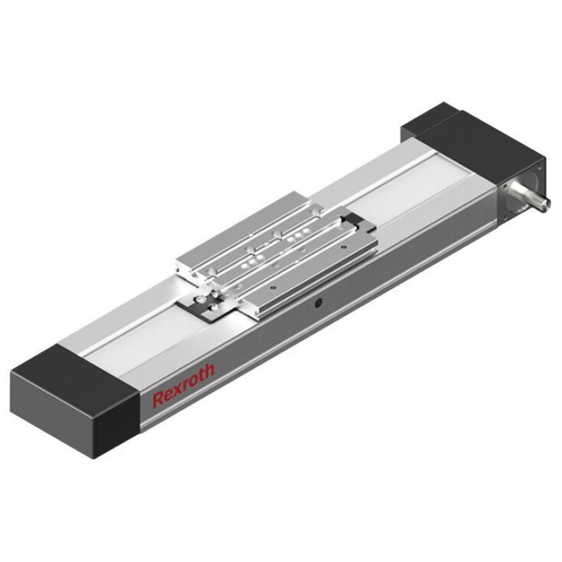
Доступно к заказу
Цена по запросу
И выбери подходящего.
Description
Product description
Structure and attachments
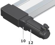
Motor attachment – direct attachment with i = 1
The motor is attached directly to the compact module’s drive end enclosure via a motor mount.
Motor attachment – with gear
The planetary gearbox is attached by a mount. The mount serves to fasten the gearbox to the CRK and as a closed housing. Due to the connection without coupling, the drive torque is transferred to the drive shaft of the Compact Module with minimal torsional deflection. Available gear ratios: i = 3 (for CKR-145 and CKR-200), i = 5, i = 10

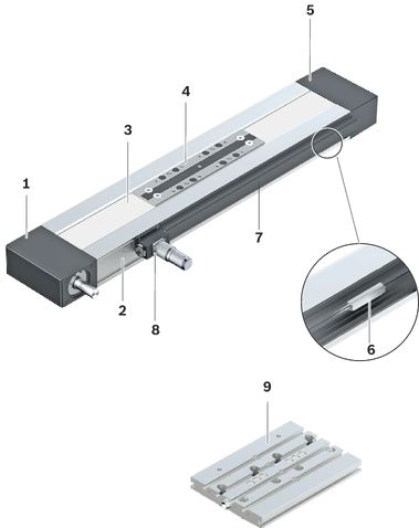
Structural design
1 Drive end enclosure
2 Frame
3 Belt drive
4 Carriage
5 Non-drive end enclosure
Additional components
6 Magnetic sensor
7 Mounting duct
8 Socket/plug
9 Connection plate
10 Flanged type
11 Planetary gearbox
12 Motor
Attachments
- Planetary gearbox with various gear ratios
- Maintenance-free servo motors with selectable brake and attached feedback
- Switches (magnetic sensors), switch activation without additional switch flag
- Socket and plug
- Mounting duct made of aluminum for sensors
Design/options for guideway (frame), carriages, connection plates, see section “Dimensions”

| 1) | Guideway (frame) |
| 2) | Carriages |
| 3) | Connection plates |
Lubrication versions
Lube version LSS, LPG
- Grease lubrication with manual grease gun via frame, carriage or via connection plate

| 1) | Connection plates |
A Drive side
Lube version LCF, LCO
- 2 lube connections
- Prepared for connection to central lubrication systems

A Drive side
1 Lube connection, Runner Block left
2 Lube connection, Runner Block right
Notes:
LSS:
- Initial lubrication by Bosch Rexroth
- Relubrication using manual grease gun
LPG:
- Ball Rail System and Ball Screw Assembly only with corrosion prevention
- Relubrication using manual grease gun
- Basic lubrication required
LCF:
- Prepared for connection to central lubrication systems for liquid grease (NLGI grade 00 in accordance with DIN 51818)
- • Lubrication with liquid grease only via single-line piston distributor system
- Basic lubrication required
LCO:
- Prepared for connection to central lubrication systems for oil
- Oil lubrication only via single-line piston distributor system
- Runner Block and Ball Screw Assembly nut with integrated non-return valves
- Basic lubrication required
Technical data
Suitable loads
Regarding the desired service life, loads for Fmgw, Fmbsshould not exceed around 20 % of the dynamic characteristic values (Cgw, Cbs).
See Chapter "Project planning notes", document "Calculation".
Do not exceed the technical data for the Linear Motion System.
Note on dynamic load capacities and moments (see the table)
Determination of the dynamic load ratings and moments is based on a total travel of 100,000 m.
Often only 50,000 m are actually stipulated. For comparison: Multiply values C, Mt and ML from the table by 1.26.
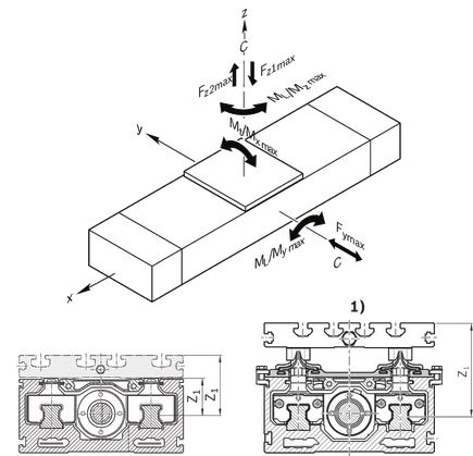
| 1) | Applicable to CKK-110, -145, -200 with Resist cover |
Note: Observe the document "Calculation" in the section "Project planning notes".
Load capacities and moments
| Size | CKR-145 | |||
| Lca | without connection plate 1) | mm | 180 | 240 |
| With connection plate 2) | mm | 125 | 190 | |
| Cgw | N | 46800 | 76025 | |
| ly | cm⁴ | 87.5 | ||
| lz | cm⁴ | 903.9 | ||
| Mt | Nm | 2059 | 3345 | |
| ML | Nm | 400 | 3801 | |
| Mx max | Nm | 634 | 1267 | |
| My max | Nm | 100 | 1440 | |
| Mz max | Nm | 100 | 683 | |
| Fy max | N | 8410 | 13660 | |
| Fz1 max | N | 14400 | 28800 | |
| Fz2 max | N | 14400 | 28800 | |
| Z1 | without connection plate | mm | 37.5 | |
| With connection plate | mm | 57.5 | ||
| 1) | In the carriage design “without connection plate” the carriage length Lca corresponds to the length of the clamping surface. |
| 2) | The connection plate is mounted on the carriage design “without connection plate.” For the design with connection plate, the carriage length Lca corresponds to the length of the connection plate. |
Note: Observe the document "Calculation" in the section "Project planning notes".
General technical data
| Size | CKR-145 | |||
| Lca | without connection plate 1) | mm | 180 | 240 |
| With connection plate 2) | mm | 125 | 190 | |
| Lad | without connection plate | mm | 25 | |
| With connection plate | mm | 80 | 75 | |
| smin 3) | mm | 60 | ||
| Lmax | mm | 5500 | ||
| mca | without connection plate | kg | 0.99 | 1.67 |
| With connection plate | kg | 1.8 | 2.82 | |
| 1) | In the carriage design “without connection plate” the carriage length Lca corresponds to the length of the clamping surface. |
| 2) | The connection plate is mounted on the carriage design “without connection plate.” For the design with connection plate, the carriage length Lca corresponds to the length of the connection plate. |
| 3) | Minimum required travel distance to ensure a reliable lubrication distribution. |
Length calculation
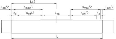

For length calculation values, see the "General Technical Data" table.
Modulus of elasticity E of the Linear Motion System

Effective stroke
Stroke: Maximum distance from carriage center to the outer-most switch activation points.
Excess travel: Excess travel must be greater than braking distance. The acceleration travel can be adopted as the guideline value for the braking distance.
Mass of the Linear Motion System
Weight calculation:
- without motor
- without switch mounting
- without motor attachment

Note: Observe the document "Calculation" in the section "Project planning notes".
Drive data
| Size | Gearbox | i | Mp | u | vmax |
| Lca | mca | kg fix | kg var | kJ fix | kJ var | kJ m | MRs | d3 | Bt | Fbp1) | Ft zul2) | amax | |||
| without connection plate | With connection plate | without connection plate | With connection plate | without connection plate | With connection plate | |||||||||||||||||
| Nm | mm/U | m/s | mm | mm | kg | kg | kg | kg/mm | kgmm2 | kgmm2 | kgmm | mm2 | Nm | mm | N | N | m/s2 | |||||
| CKR-145 | - | 1 | 32,50 | 165,0 | 5,00 |  | 180 | 125 | 0,99 | 1,80 | 2,54 | 0,01222 | 1024,28 | 1582,85 | 0,3172 | 689,59 | 1,46 | 52,52 | 70 AT5 | 1235 | 4800 | 50 |
| PG070 | 3 | 11,00 | 55,0 | |||||||||||||||||||
| 5 | 6,70 | 33,0 | 240 | 190 | 1,67 | 2,82 | 1621,61 | 2276,71 | 2,04 | |||||||||||||
| 10 | 3,35 | 16,5 | 2,92 | |||||||||||||||||||
| 1) | Maximum power that can be transmitted through the engaging teeth that are in the belt pulley. |
| 2) | The maximum permitted tensile load on the belt cross section (belt elasticity limit) is given here for easier comparability. This value represents the load limit in terms of plastic deformation and may not be used to calculate the maximum permissible drive torque. |
Mass moment of inertia of the linear system

Determination of translative mass moment of inertia of the external load

Note: Observe the document "Calculation" in the section "Project planning notes".
Getriebedaten
| Size | Gearbox | Mge1) | MRge | nge | Motor | Jge | mge | |
| Type | i | Nm | Nm | rpm | Type | kgm2 | kg | |
| CKR-145 | PG070 | 3 | 32 | 0,24 | 8000 | MS2N04 | 0,0000320 | 2,1 |
| MS2N05 | 0,0000530 | 3,2 | ||||||
| MSM041-B | ||||||||
| 5 | 40 | 0,17 | MS2N04 | 0,0000270 | 2,1 | |||
| MS2N05 | 0,0000460 | 3,2 | ||||||
| MSM041-B | ||||||||
| 10 | 35 | 0,12 | MS2N04 | 0,0000220 | 2,1 | |||
| MS2N05 | 0,0000430 | 3,2 | ||||||
| MSM041-B | ||||||||
| 1) | The limit values of the Linear Motion System must not be exceeded, see “Calculation” document in the "Project planning instructions" chapter. |
Normal operating conditions
| Size | CKR-145 | |
| Permissible ambient temperature with Rexroth servo motor 1) | 0 °C ... +40 °C | |
| Permissible ambient temperature for mechanical system 2) | -10 °C ... +60 °C | |
| smin 3) | mm | 60 |
| 1) | Performance losses from 40°C |
| 2) | No passing below the dew point |
| 3) | Minimum required travel distance to ensure a reliable lubrication distribution. |
Note: Application of dirt is not permitted!
Legend
| Symbol | Description | Unit |
| amax | Maximum acceleration travel | m/s2 |
| Cgw | Dynamic load capacity, linear guide | N |
| d3 | Diameter, belt pulley | mm |
| Fbp | Maximum belt drive transmission force | N |
| Fmbs | Dynamic equivalent load on bearing of the Ball Screw Assembly | N |
| Fmgw | Dynamic equivalent load on bearing of the guideway | N |
| Ft zul | Belt elasticity limit | N |
| Fy max | Maximum dynamic load in y-direction | N |
| Fz1 max | Maximum dynamic load in z-direction | N |
| Fz2 max | Maximum dynamic load in z-direction | N |
| i | Transmission | - |
| ly | Y-axis planar moment of inertia | cm4 |
| lz | Z-axis planar moment of inertia | cm4 |
| Js | Mass moment of inertia of the linear system | kgm2 |
| Jge | Mass moment of inertia of the gear on the motor journal | kgm2 |
| Jt | Translatory mass moment of inertia of external load based on the Linear Motion System screw journal | kgm2 |
| kg fix | Constant for fixed portion of the mass | kg |
| kg var | Constant for variable-length portion of the mass | kg/mm |
| kJ fix | Constant for fixed-length portion of mass moment of inertia | kgmm2 |
| kJ m | Constant for mass-specific portion of mass moment of inertia | mm2 |
| kJ var | Constant for variable-length portion of mass moment of inertia | kgmm |
| L | Length of linear motion system | mm |
| Lad | Additional length | mm |
| Lca | Carriage length | mm |
| Lmax | Maximum length | mm |
| mca | Moved mass of system of carriage | kg |
| mex | Moved external mass | kg |
| mge | Mass of the gear | kg |
| Mge | Maximum permissible acceleration torque of the gear (on the output drive) | Nm |
| ML | Dynamic longitudinal moment load capacity | Nm |
| Mp | Max. permissible drive torque (at drive journal) | Nm |
| MRge | Friction moment of belt side drive at motor journal | Nm |
| MRs | Frictional torque of system | Nm |
| ms | Mass of the Linear Motion System (without attachments) | kg |
| Mt | Dynamic torsional moment load capacity | Nm |
| Mx max | Maximum admissible torsional moment around the x-axis | Nm |
| My max | Maximum admissible torsional moment around the y-axis | Nm |
| Mz max | Maximum admissible torsional moment around the z-axis | Nm |
| nge | Maximum permissible speed of the gear | rpm |
| PG | Planetary gearbox | - |
| se | Excess travel (excess travel se should be greater than braking distance. The acceleration travel can be used as a guideline for braking distance.) | mm |
| seff | Effective stroke | mm |
| smax | Maximum travel range | mm |
| smin | Minimum travel | mm |
| u | Lead constant | mm/U |
| vmax | Maximum permissible speed | m/s |
| Z1 | Application point of the effective force | mm |
Dimensions
Straightness and flatness tolerance in accordance with DIN EN 12020-2.
Notes: All dimensions are given in mm. Drawings not schematically to scale.
Exact contours and dimensions can be found in the CAD model.
For dimensional drawings for motor attachment, see Chapter "Motor attachment".
For the length calculation of the Linear Motion System see Chapters “Technical data” and “Project planning notes”, document “Calculation”.
Frame dimension drawings

| 1) | Lubrication bore on both sides (grease lubrication). For more information, see section “Maintenance” |
| 2) | deep |
| 3) | Version |
| TT | Carriage |
Dimensions
| Size | CKR-145 | ||
| b | P9 | mm | 6 |
| ⌀d | h7 | mm | 19 |
| ⌀D | H7 | mm | 49 |
| ⌀D1 | H7 | mm | 24 |
| h | mm | 3.5 | |
| H3 | mm | 32 | |
| K1 | M6 | ||
| K2 | mm | 12 | |
| K3 | mm | 45 | |
| K4 | mm | 45 | |
| K5 | mm | 30.5 | |
| Toleranz für K5 | mm | ± 0.1 | |
| K6 | mm | 30 | |
| K7 | M5 (ISO 4762) | ||
| L1 | mm | 61 | |
| L2 | mm | 64 | |
| L3 | mm | 71.5 | |
| L4 | mm | 40 | |
| L5 | mm | 2 | |
| L6 | mm | 2.5 | |
| L7 | mm | 27.5 | |
| L8 | mm | 9 | |
| Tolerance for L8 | mm | ± 0.1 | |
| L9 | mm | 20 | |
| L10 | mm | 17.5 | |

| 1) | For connection plate, see section “Accessories” |
| A | For switch mounting arrangements |
| B | For mounting with clamping fixtures |
Dimensions
| Size | CKR-145 | |
| A | mm | 145 |
| H | mm | 65 |
| H1 | mm | 85 |
| H2 | mm | 64 |
| N1 | mm | 9.5 |
Option 01 / standard
View from below (ground area)

Option 03 / with central holes
View from below (ground area)

| 1) | deep |
Dimensions, option 03
| Size | CKR-145 | ||
| B1 | M6 | ||
| B2 | mm | 13 | |
| ⌀B3 | H7 | mm | 12 |
| B4 | cm | 2.1 | |
| L1 | mm | 20 | |
| L2 | cm | 40 | |
| Tolerance for L2 | mm | ± 0.01 | |
| L3 | min | mm | 10 |
| L4 | mm | 30 | |
| L5 | mm | 35 | |
| L6 | mm | 124 | |
Option 04 / with central holes and long hole
View from below (ground area)

| 1) | deep |
Dimensions, option 04
| Size | CKR-145 | ||
| ⌀B3 | H7 | mm | 12 |
| B4 | cm | 2.1 | |
| B5 | H8 | mm | 12 |
| L1 | mm | 20 | |
| L2 | cm | 40 | |
| Tolerance for L2 | mm | ± 0.01 | |
| L7 | mm | 60 | |
Carriage dimension drawings
Carriage without connection plate
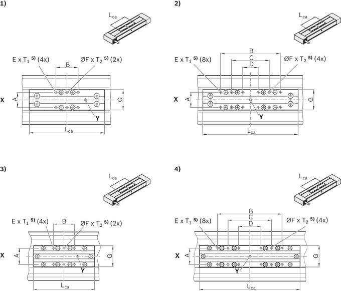
| 1) | Fig. 1 |
| 2) | Fig. 2 |
| 3) | Fig. 3 |
| 4) | Fig. 4 |
| 5) | deep |
| X | Drive side |
| Y | Lubrication option for grease; closed with set screw. |
Dimensions
| Size | CKR-145 | |||
| Picture | 1 | 2 | ||
| Lca | mm | 180 | 240 | |
| A | mm | 48 | ||
| B | mm | 60 | 160 | |
| C | mm | - | 100 | |
| D | mm | - | 40 | |
| E | M6 | |||
| ⌀F | H7 | mm | 6 | |
| G | mm | 62 | ||
| T1 | mm | 12 | ||
| T2 | mm | 7.5 | ||
Carriages with connection plate
Dimension diagrams, see section “Accessories,” connection plates

Legend
| Symbol | Description | Unit |
| L | Length of linear motion system | mm |
| Lad | Additional length | mm |
| Lca | Carriage length | mm |
| LW | Center-to-center distance between carriages | mm |
| se | Excess travel (excess travel se should be greater than braking distance. The acceleration travel can be used as a guideline for braking distance.) | mm |
| seff | Effective stroke | mm |
| smax | Maximum travel range | mm |
Project planning information
Calculation
Calculation example
Mounting
Caution! Do not secure or support the Compact Module at the end enclosures! The frame is the load-bearing part!
Mounting with clamping fixtures

| 1) | For Compact Modules with centering holes in the ground area (selection via the guideway option): Use centering rings to better align to other Linear Motion Systems and connection elements. |
| Size | A | B |
| mm | mm | |
| 070 | 82 | 95 |
| 090 | 102 | 112 |
| 110 | 126 | 140 |
| 145 | 161 | 175 |
| 200 | 222 | 240 |
Mounting by means of special modification in the base surface of the frame is possible
Guideway option 03 already includes threaded holes in the ground area of the frame (see dimension drawings).
Special modification in the base surface of the frame
(not available from factory)

| 1) | Pin hole or thread max. ØB |
| 2) | Distance from frame ends at least 30 mm |
| 3) | Max. C |
| Size | A | B | C |
| mm | mm | mm | |
| 070 | 59 | 3 | 7,5 |
| 090 | 76 | 4 | 7,5 |
| 110 | 92 | 5 | 9,0 |
| 145 | 124 | 6 | 13,0 |
| 200 | 119 | 8 | 12,0 |
Magnetic sensor with free cable end
1 Socket and plug
2 Sensor
3 Mounting duct
Alternatively, the sensor can also be attached by switch mounting plate and cable holder.
See the magnetic sensor with plug.
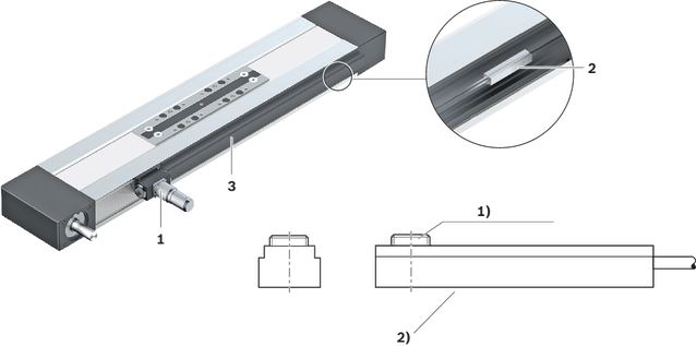
| 1) | Set screw for retention |
| 2) | Active surface |
Additional component/actuation
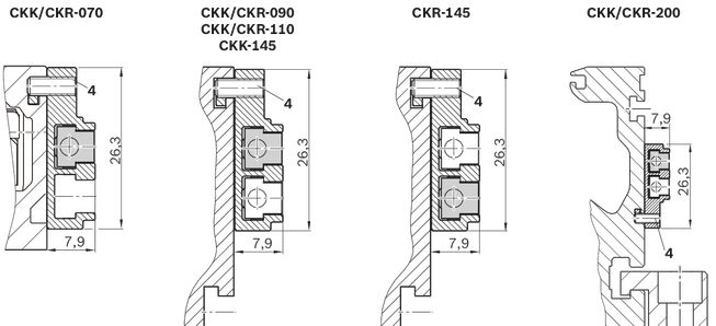
A mounting duct is needed to fasten the sensors and cable guides. This is suspended at the side in a slot at the Compact Module and secured with set screws (4).
The set screws are included.
The sensors are pushed into the upper T-slot (CKK/CKR-090,-110 and CKK-145) or into the lower T-slot (CKR-145, CKK/CKR-200) of the mounting duct and secured with set screws.
Switch activation is done by magnets in the carriage.

Socket - plug
Notes:
Socket and plug are not wired.
This allows optimal assignment of switching positions during start-up.
One plug is included.
The plug can be installed in three directions.
For further information, see the "Socket - plug” view.

Magnetic sensor with plug
1 Sensor
2 Switch mounting plate including set screws (loose) and square nut 2a
3 Cable holder including set screw (loose)
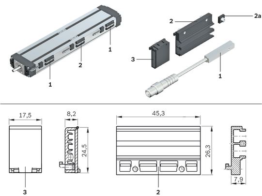
Attachment/Actuation
A switch mounting plate (2) is required to attach the sensors. This is suspended in the upper slot on the Compact Module and secured with set screws (4).
The sensors are pushed into the respective slot on the switch mounting plate and secured with one set screw.
The square nut with set screw (2a) serves as a fixed stop for the sensor (switching position when changing sensors). Parts are included in the scope of delivery of the sensor mounting kit.
Switch activation is done by magnets in the carriage.
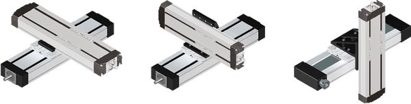
Compact Modules fit together perfectly – fast and flexible
Minimal mounting times, maximum efficiency:
Standardized interfaces significantly reduce the effort during mounting.
The mechanical systems have positive-locking interfaces throughout.
They can be quickly and accurately connected together without time-consuming alignment.
The result:
Users can respond flexibly to handling the different applications and tasks.
For more information about connection technology, see Connection technology for Linear Motion Systems and linear axes.
Connection technology for Linear Motion Systems
Commissioning
Parameterization (start-up)
The nameplate contains reference information on the production of the linear motion system as well as technical start-up parameters.

Legend
| Position | Symbol | Description | Unit |
| 1 | CNR | Customer's part number | - |
| 2 | TYP | Short product name | - |
| 3 | 110 | Frame size | - |
| 4 | CS | Customer information | - |
| 5 | MNR | Part number | - |
| 6 | FD | Date of production | - |
| 7 | 7210 | Manufacturing location | - |
| 8 | smax | Maximum travel range | mm |
| 9 | u | Lead constant without motor attachment | mm/U |
| 10 | vmax | Maximum speed | m/s |
| 11 | amax | Maximum acceleration travel | m/s2 |
| 12 | M1max | Maximum drive torque on the motor journal | Nm |
| 13 | d | Direction of motor rotation to move in positive (+) direction 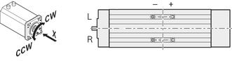 | - |
| 14 | i | Transmission ratio | - |
| 15 | - | QR code | - |
Maintenance
Lubricant
Lubrication CKR
Delivery notes
Form of delivery
Compact Modules with Ball Rail System and belt drive are delivered completely assembled.
Motor attachment
If a combination of motor and motor attachment has been selected, then the components are attached as shown in the figure, which also shows the location of the motor connector.
When ordering motor attachments without motor, not all parts can be mounted. Assembly must then be completed by the customer. All necessary instructions and parameters for professional assembly are included.
Direct attachment (MA10, MA11)

| 1) | Linear motion system |
| 2) | Motor connector |
| 3) | Motor |
| 4) | Direct attachment (flange) |
Planetary gearboxes (MG10, MG11, MG01-MG04)

| 1) | Linear motion system |
| 2) | Motor connector |
| 3) | Motor |
| 4) | Gearbox |
Available options
Cable duct, mounting duct, switch, switching angle and socket with plugs are included as loose parts.
Lubrication
Compact Modules are delivered with initial greasing, depending on the lubricant used.
For more information on lubricants, see Chapter "Lubrication".
Documentation
Each Compact Module is supplied with the accompanying documentation.
Safety Instructions
Motor attachment
Measurement and test reports
Downloads
 | Declaration of Incorporation for single axis Linear Motion Systems Certificate | R320103141 | 2020-06-01 | All languages | PDF | 409k Product Groups: Linear axes and electromechanical cylinders |
| Safety Instructions for Linear Motion Systems Manual | R320103152_en | 2015-01-01 | English | PDF | 593k Product Groups: Linear axes and electromechanical cylinders |
| Compact Modules CKK, CKR Catalog | R999000499 | 2022-02-01 | English | PDF | 24.8MB Product Groups: Compact Modules Compact Modules CKK, CKR |

Нет отзывов об этом товаре.