
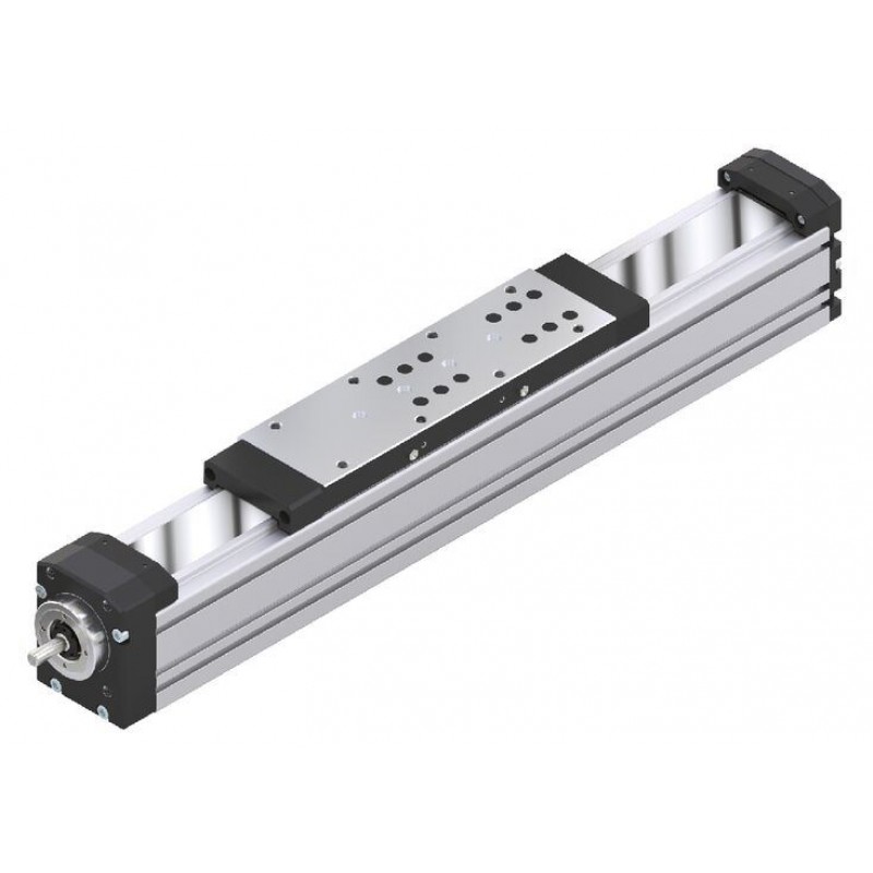
Доступно к заказу
Цена по запросу
И выбери подходящего.
Description
Product description
Types
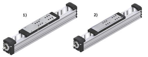
| 1) | Carriage with thread |
| 2) | Carriage with T-slots |

| 1) | Motor mounting with timing belt side drive |
| 2) | Motor mounting with flanged-type coupling |
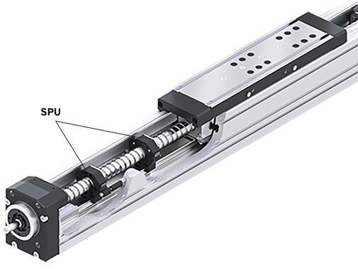
Screw support (SPU) for MKK-080-NN-3, MKK-110-NN-3 and MKK-140-NN-3
The Screw Support (SPU) offers the following advantages:
- Screw support for horizontal applications (in preparation for vertical applications)
- Screw support can be selected as standard option via the option number.
- A maximum of two screw support pairs is possible.
- High speed over long lengths of up to 5400 mm.
- Guide of the screw supports in the main body.
- Screw supports are maintenance-free.
- Screw supports are protected by optionally selectable sealing strip.
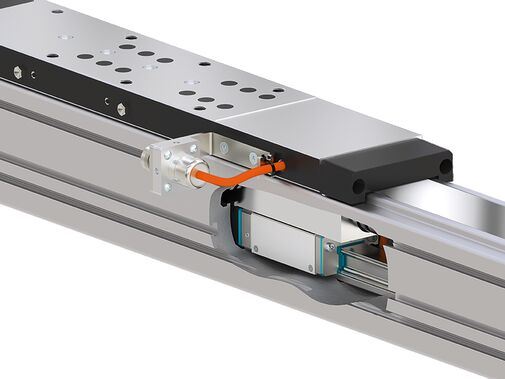
Integrated Measuring System for MKK-080-NN-3, MKK-110-NN-3 and MKK-140-NN-3
The IMS-A measuring system offers the following advantages:
- No additional space required.
- No external mounting surfaces required for the measuring system.
- No measuring inaccuracies due to deviations in parallelism between the measuring system and the guide system
- Full integration of the measuring system components into the guide means no complex assembly or tuning work is needed
- The runner block, measuring head and guide rail with scale can be replaced individually during servicing.
- Interfaces: HIPERFACHE or DRICE-CLiQ.
- Connection cable directly on the side of the carriage.
Material pairing
ALST:
- Main body, carriage and end plates made of anodized aluminum (AL)
- MKK-065/-080/-110/-140: Ball rail, ball runner block and ball screw assembly made of rolling bearing steel (ST)
- MKK-040: Ball rail and ball runner block of rust and acid resistant material. Ball screw assembly made of rolling bearing steel (ST)
- Angular-contact ball bearing and grooved ball bearing of the screw drive bearing made of rolling bearing steel
ALCR:
- Main body, carriage and end plates made of anodized aluminum (AL)
- MKK-065/-080/-110/-140: Ball rail and ball screw assembly made of rolling bearing steel with corrosion resistant coating, matte-silver finish, hard chrome plated (Resist CR), ball runner block from corrosion resistant steel (Resist NR)
- MKK-040: Ball rail and ball runner block of rust and acid resistant material. Ball screw assembly made of rolling bearing steel with corrosion resistant coating, matte-silver finish, hard chrome plated (Resist CR)
- Angular-contact ball bearing and grooved ball bearing of the screw drive bearing made of rolling bearing steel
Lubrication variants
LSS: (Initial lubrication done at the factory)
- Initial standard greasing done at the factory, suitable for normal ambient conditions.
- Simple relubrication via manual grease gun.
MKK-065, MKK-080, MKK-110, MKK-140:
- Grease lubricant Dynalub 510, lithium-based high-performance grease of the NLGI grade 2 according to DIN 51818 (KP2K-20 according to DIN 51825)
MKK-040:
- Grease lubricant Dynalub 520, lithium-based high-performance grease of the NLGI grade 00 according to DIN 51818 (GP00K-20 according to DIN 51826)
LPG: (Corrosion prevention, no initial lubrication)
- Linear module without initial greasing done at the factory.
- Ball rail system and ball screw assembly only with corrosion prevention
- Basic lubrication required
LCF: (prepared for connection to central lubrication systems with liquid grease)
- for liquid grease, NLGI grade 00 lithium-based high-performance grease according to DIN 51818 (GP00K-20 according to DIN 51826)
- Liquid grease lubrication via single-line piston distributor system only
- Basic lubrication required
LCO: (prepared for connection to central lubrication systems with oil)
- ball runner block and ball screw drive nut with integrated non-return valves
- Only use oil lubrication with single-line total-loss lubrication systems via piston distributors.
- Basic lubrication required
Structure and attachments

Structural design
1 Ball screw assembly (BASA) with zero-backlash cylindrical single nut
2 End block fixed bearing
3 Cover strip for MKK-040/-065/-080/-110/-140
4 Carriage with runner blocks
5 Strip fixing
6 End plate floating bearing
7 Main body
Attachments
8 Switch bracket
9 Proximity switch
10 Mechanical switch
11 Cable channel
12 Socket/plug
13 Bellows cover for MKK-165
14 Magnetic field sensor

15 Mount
16 Servo motor
17 Timing belt side drive
Motor attachment with mount and coupling
A motor can be attached via a mount and coupling to all linear modules equipped with a ball screw drive.
The mount serves to fasten the motor to the Linear Module and acts as a closed housing for the coupling.
The coupling transmits the motor drive torque free of distortive stresses to the Linear Module’s drive shaft.
Our standard couplings compensate for the system’s thermal expansion.

1 Motor
2 Mount
3 Coupling
4 Linear module
Motor attachment via timing belt side drive
On all linear modules with a ball screw drive the motor can be attached via a timing belt side drive.
This makes the overall length shorter than when attaching the motor with a mount and coupling.
The space-saving, closed pulley housing provides protection for the belt and acts as a motor bracket.
In addition, various gear ratios are available.
The timing belt side drive can be mounted in four different directions.

1 Pulley housing made of anodized aluminum
2In some cases with support bearing for Rexroth Ball Screw Assembly screw journal.
3 Linear module
4 Belt drive with gear ratio: i = 1; i = 1,5; i = 2
5 Servo motor
6 Pre-tensioning of the belt drive: Apply preload force Fpr to the motor (Fpr is stated upon delivery).
7 Cover
8 Belt pulleys attached using tensioning units
9 Cover plate
Technical data
General technical instructions
Note on dynamic load capacities and load moments
Determination of the dynamic load capacities and load moments is based on a travel life of 100 000 m. Often only 50 000 m is actually stipulated.
For comparison:
Multiply values C, Mt and ML from the table by 1.26.
Suitable loads
Regarding the desired nominal life, in general loads for Fcomb, Fm up to around 20 % of the dynamic characteristic values (C, Mt, ML) have generally proven suitable.
See the "Calculation" document in the "Project planning instructions" chapter for the respective Linear Module.
Do not exceed the technical data for the Linear Motion System.

Application point of the effective force (Z1)

Modulus of elasticity E of the Linear Motion System

General technical instructions
Length calculation of the Linear Motion System


For length calculation values, see the "General Technical Data" table.
Note: Adhere to the section "General technical instructions" and the document "Calculation" in the chapter "Project planning instructions".
Load capacities and moments
| Size | MKK-080 | |||||||||||||
| Version | without IMS | with IMS | variable centerline-to-centerline distance | |||||||||||
| Number of carriages | 1 | 2 | ||||||||||||
| Lca | without IMS | mm | 260 | 260 1) | 260 | |||||||||
| with IMS | mm | - | 360 2) 3) | - | ||||||||||
| LW | min | mm | - | 320 4) | ||||||||||
| max | mm | - | 960 4) | |||||||||||
| d0 x P | mm | 20 x 5 | 20 x 10 | 20 x 20 | 20 x 40 | 20 x 5 | 20 x 10 | 20 x 20 | 20 x 40 | 20 x 5 | 20 x 10 | 20 x 20 | 20 x 40 | |
| Cgw | N | 38000 | 76000 | |||||||||||
| Cbs | N | 15480 | 15210 | 14400 | 12600 | 15480 | 15210 | 14400 | 12600 | 15480 | 15210 | 14400 | 12600 | |
| Cfb | N | 16900 | ||||||||||||
| Mt | Nm | 487 | 974 | |||||||||||
| ML | Nm | 1843 | 19 x Lw 5) | |||||||||||
| Mx max | Nm | 195 | 390 | |||||||||||
| My max | Nm | 737 | 7,5 x Lw 6) | |||||||||||
| Mz max | Nm | 737 | 7,5 x Lw 6) | |||||||||||
| Fy max | N | 15200 | 30400 | |||||||||||
| Fz1 max | N | 15200 | 30400 | |||||||||||
| Fz2 max | N | 15200 | 30400 | |||||||||||
| Z1 | mm | 74 | ||||||||||||
| ly | cm⁴ | 183 | ||||||||||||
| lz | cm⁴ | 213 | ||||||||||||
| 1) | Note: For the length calculation when using IMS, use value Lca with IMS. |
| 2) | Value for length calculation |
| 3) | Clamping surface corresponds to Lca (without IMS) |
| 4) | Centerline-to-centerline distance specified according to customer design. Centerline-to-centerline distance freely selectable between minimum and maximum distance in millimeter increments. |
| 5) | Dyn. longitudinal load moment ML with variable carriage centerline-to-centerline distance according to the chosen centerline-to-centerline distance. |
| 6) | Determine maximum permissible longitudinal moments My max and Mz max with variable carriage centerline-to-centerline distance according to the chosen centerline-to-centerline distance. |
General technical data
| Size | MKK-080 | |||||||||||||
| Version | without IMS | with IMS | variable centerline-to-centerline distance | |||||||||||
| Number of carriages | 1 | 2 | ||||||||||||
| Lca | without IMS | mm | 260 | 260 1) | 260 | |||||||||
| with IMS | mm | - | 360 2) 3) | - | ||||||||||
| LW | min | mm | - | 320 4) | ||||||||||
| max | mm | - | 960 4) | |||||||||||
| d0 x P | mm | 20 x 5 | 20 x 10 | 20 x 20 | 20 x 40 | 20 x 5 | 20 x 10 | 20 x 20 | 20 x 40 | 20 x 5 | 20 x 10 | 20 x 20 | 20 x 40 | |
| Lad | without screw support | mm | 109 | |||||||||||
| Screw supports, 1 pair | mm | 122 | ||||||||||||
| Screw supports, 2 pairs | mm | 168 | ||||||||||||
| smin 5) | mm | 60 | ||||||||||||
| Lmax | without screw support | mm | 2500 | |||||||||||
| with screw support | mm | 3400 | ||||||||||||
| mca | kg | 2.91 | 2.86 | 3.14 | 3.2 | 3.31 | 3.26 | 3.54 | 3.6 | 5.61 | 5.56 | 5.84 | 5.9 | |
| kg fix | kg | 2 | ||||||||||||
| kg var | kg/mm | 0.0117 | ||||||||||||
| Repeatability (up to ...) | mm | ± 05 | ||||||||||||
| 1) | Note: For the length calculation when using IMS, use value Lca with IMS. |
| 2) | Value for length calculation |
| 3) | Clamping surface corresponds to Lca (without IMS) |
| 4) | Centerline-to-centerline distance specified according to customer design. Centerline-to-centerline distance freely selectable between minimum and maximum distance in millimeter increments. |
| 5) | Minimum required travel to ensure a reliable lubrication distribution! If this cannot be achieved, please consult Bosch Rexroth. |
Note: Adhere to the section "General technical instructions" and the document "Calculation" in the chapter "Project planning instructions".
Drive data
| Size | MKK-080 | ||||||||||||
| Version | without IMS | with IMS | variable centerline-to-centerline distance | ||||||||||
| Number of carriages | 1 | 2 | |||||||||||
| Lca | mm | 260 | 260 1) | 260 | |||||||||
| d0 x P | mm | 20 x 5 | 20 x 10 | 20 x 20 | 20 x 40 | 20 x 5 | 20 x 10 | 20 x 20 | 20 x 40 | 20 x 5 | 20 x 10 | 20 x 20 | 20 x 40 |
| mca | kg | 2.91 | 2.86 | 3.14 | 3.2 | 3.31 | 3.26 | 3.54 | 3.6 | 5.61 | 5.56 | 5.84 | 5.9 |
| kJ fix | kg·mm² | 11.226 | 16.628 | 41.223 | 139.057 | 11.479 | 17.651 | 45.276 | 155.268 | 12.936 | 23.467 | 68.58 | 248.48 |
| kJ var | kg·mm | 0.084 | 0.081 | 0.086 | 0.084 | 0.081 | 0.086 | 0.084 | 0.081 | 0.086 | |||
| kJ m | mm² | 0.633 | 2.533 | 10.14 | 40.53 | 0.633 | 2.533 | 10.14 | 40.53 | 0.633 | 2.533 | 10.14 | 40.53 |
| MRs 2) | Nm | 0.4 | 0.5 | 0.7 | 0.4 | 0.5 | 0.7 | 0.5 | 0.55 | 0.6 | 0.8 | ||
| amax | m/s² | 39.8 | 50 | 27 | 39.8 | 50 | 27 | 39.8 | 50 | 27 | |||
| 1) | Note: For the length calculation when using IMS, use value Lca with IMS. |
| 2) | at 200 min-1 |
Values also valid for the carriage version with variable centerline-to-centerline distance.
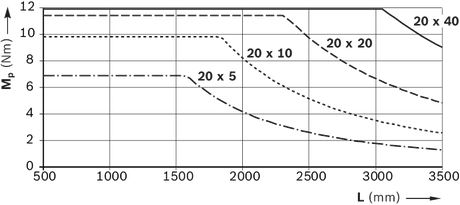
Note: For the max. drive torque Mp and max. speed vmax see section on "Diagrams / Characteristic curves".
Drive data for motor attachment using the timing belt side drive
| Size | Motor | d0 x P | up to L1) | Msd2) | Jsd | MRsd | msd | Bt | ||||||||
| mm | mm | Nm | 10‑6 kgm2 | Nm | kg | |||||||||||
| i = 1 | i = 1,5 | i = 2 | i = 1 | i = 1,5 | i = 2 | i = 1 | i = 1,5 | i = 2 | i = 1 | i = 1,5 | i = 2 | |||||
| MKK-080 | MSM 041B MS2N 04 | 20 x 5 | 1600 | 5,90 | 3,90 | - | 250,0 | 85,0 | - | 0,40 | 1,24 | 1,27 | - | 16 AT5 | 16 AT5 | - |
| 20 x 10 | 2000 | 7,60 | 5,00 | - | ||||||||||||
| 20 x 20 | 2500 | 8,30 | 5,50 | - | ||||||||||||
| 20 x 40 | 2500 | 8,50 | 5,70 | - | ||||||||||||
| MS2N05 | 20 x 5 | 1600 | 5,90 | - | 2,95 | 1420,0 | - | 230,0 | 0,45 | 3,20 | - | 2,90 | 25 AT5 | - | 25 AT5 | |
| 20 x 10 | 2000 | 7,70 | - | 3,85 | ||||||||||||
| 20 x 20 | 2500 | 8,50 | - | 4,25 | ||||||||||||
| 20 x 40 | 2500 | 8,70 | - | 4,35 | ||||||||||||
| 1) | For longer lengths, the permissible drive torque is determined from the variable-length value Mp of the linear motion system as per the diagram. See the chapter "Project planning instructions" |
| 2) | Values for Msd without making allowance for the motor torque. |
Drive data for motor attachment via mount and coupling
| Size | Motor | Coupling | Mount and coupling | ||
| McN | Jc | mc | mfc | ||
| Nm | 10‑6 kgm2 | kg | kg | ||
| MKK-080 | MS2N 04 | 19,0 | 57,0 | 0,26 | 1,0 |
| MS2N 05 | 50,0 | 210,0 | 0,70 | 1,9 | |
| MSM 041B | 14,5 | 63,0 | 0,26 | 0,9 | |
Normal operating conditions
| Size | MKK-080 | |
| Permissible ambient temperature with Rexroth servo motor 1) | 0 °C ... +40 °C | |
| Permissible ambient temperature for mechanical system 2) | -10 °C ... +60 °C | |
| smin 3) | mm | 60 |
| 1) | Performance losses from 40°C |
| 2) | No passing below the dew point |
| 3) | Minimum required travel to ensure a reliable lubrication distribution! If this cannot be achieved, please consult Bosch Rexroth. |
Note: Application of dirt is not permitted!
Legend
| Symbol | Description | Unit |
| amax | Maximum acceleration travel | m/s2 |
| Bt | Belt type | - |
| Cbs | Dynamic load capacity, ball screw drive | N |
| Cfb | Dynamic load capacity, fixed bearing | N |
| Cgw | Dynamic load capacity, linear guide | N |
| d0 | Nominal diameter of ball screw drive | mm |
| Fy max | Maximum dynamic load in y-direction | N |
| Fz1 max | Maximum dynamic load in z-direction | N |
| Fz2 max | Maximum dynamic load in z-direction | N |
| i | Gear ratio | - |
| IMS | integrated measuring system | - |
| Jc | Mass moment of inertia of the coupling | kgm2 |
| Jsd | Reduced mass moment of inertia of timing belt side drive on the motor journal | kgm2 |
| kg fix | Constant for the fixed portion of the mass | kg |
| kg var | Constant for the variable-length portion of the mass | kg/mm |
| kJ fix | Constant for fixed-length portion of mass moment of inertia | kgmm2 |
| kJ m | Constant for mass-specific portion of mass moment of inertia | mm2 |
| kJ var | Constant for variable-length portion of mass moment of inertia | kgmm |
| L | Length | mm |
| Lad | Additional length | mm |
| Lca | Carriage length | mm |
| Lmax | Maximum length | mm |
| LW | Carriage center-to-center distance | mm |
| Lw max | Maximum carriage center-to-center distance | mm |
| Lw min | Minimum carriage center-to-center distance | mm |
| ly | Y-axis planar moment of inertia | cm4 |
| lz | Z-axis planar moment of inertia | cm4 |
| mc | Mass of the coupling | kg |
| mca | Moved mass of system (carriage) | kg |
| McN | Rated torque of coupling | Nm |
| mfc | Mass of mount and coupling | kg |
| ML | Dynamic longitudinal moment load capacity | Nm |
| MRs | Frictional torque of the system | Nm |
| msd | Mass of timing belt side drive | kg |
| Msd | Maximum permissible drive torque of the timing belt side drive | Nm |
| Mt | Dynamic torsional moment load capacity | Nm |
| Mx max | Maximum admissible torsional moment around the x-axis | Nm |
| My max | Maximum admissible torsional moment around the y-axis | Nm |
| Mz max | Maximum admissible torsional moment around the z-axis | Nm |
| P | Lead | mm |
| se | Excess travel | mm |
| seff | Effective travel distance | mm |
| smax | Maximum travel range | mm |
| smin | Minimum travel | mm |
| Screw support | Screw support | - |
| Z1 | Application point of the effective force | mm |
Diagrams/characteristic curves
Permissible drive torque
The values for Mp apply for the following conditions:
- Screw journal without keyway
- No radial load on screw journal
Permissible speed vmax
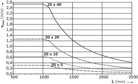
Rexroth Ball Screw Assembly 20 x 40 without screw support
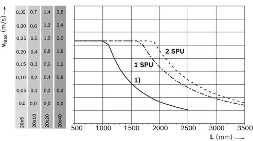
| 1) | without screw support |
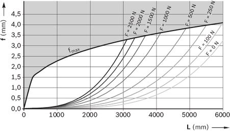
Deflection
Take note of the "General Technical Instructions" section of the "Technical Data" chapter.
Example
Linear Module MKK-080: L = 3000 mm, F = 1500 N
From diagram MKK-080: f = 1.8 mm, fmax = 3.5 mm
The deflection f is significantly less than the maximum permissible deflection fmax, and no additional support is therefore necessary.
The following diagram is valid for:
- both ends firmly fixed (200 to 250 mm per side)
- 6 to 8 screws per side
- solid mounting base
- Lmax must be noted; see the "General Technical Data" table in the "Technical Data" chapter
Dimensions
All dimensions in mm. Drawings not to scale.
Frame dimension drawings
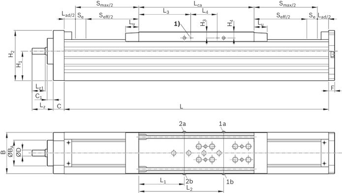
| 1) | Fastening thread M4 - 10 deep (4x) for switching angle |
1a / 1b lube fitting for ball runner block: lubrication on either of the two connections.
2a / 2b lube fitting for ball screw drive: lubrication on either of the two connections.
(lube fitting 1a/1b/2a/2b: funnel-type lube nipple DIN 3405-AM6)
For further lubrication information, see the "Maintenance" chapter.
Dimensions
| Size | MKK-080 | |||||||||||||
| Version | without IMS | with IMS | variable centerline-to-centerline distance | |||||||||||
| Number of carriages | 1 | 2 | ||||||||||||
| Lca | without IMS | mm | 260 | 260 1) | 260 | |||||||||
| with IMS | mm | - | 360 2) 3) | - | ||||||||||
| d0 x P | mm | 20 x 5 | 20 x 10 | 20 x 20 | 20 x 40 | 20 x 5 | 20 x 10 | 20 x 20 | 20 x 40 | 20 x 5 | 20 x 10 | 20 x 20 | 20 x 40 | |
| B | mm | 80 | ||||||||||||
| ØBA | mm | 55 | ||||||||||||
| C | mm | 29 | ||||||||||||
| C1 | mm | 13 | ||||||||||||
| ⌀D | mm | 10 | ||||||||||||
| F | mm | 13 | ||||||||||||
| H1 | mm | 57.5 | ||||||||||||
| H2 | mm | 98.5 | ||||||||||||
| H3 | mm | 12 | ||||||||||||
| H4 | mm | 12.7 | ||||||||||||
| L1 | mm | 76.5 | ||||||||||||
| L2 | mm | 175 | ||||||||||||
| L3 | mm | 88 | ||||||||||||
| L4 | mm | 70 | ||||||||||||
| Lu | mm | 30 | ||||||||||||
| Lz | mm | 40 | ||||||||||||
| Lz1 | mm | 27 | ||||||||||||
| 1) | Note: For the length calculation when using IMS, use value Lca with IMS. |
| 2) | Value for length calculation |
| 3) | Clamping surface corresponds to Lca (without IMS) |
Optional frame with centering holes and elongated hole on the underside
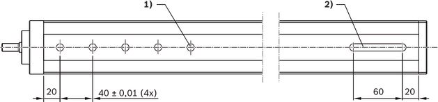
| 1) | 5 x ZH7 – T deep |
| 2) | ZH8 – T deep |

| 1) | For clamping fixtures |
| 2) | For mounting duct |
| 3) | For sensor |
| 4) | Side sealing in carriage |
Dimensions
| Size | MKK-080 | |||||||||||||
| Version | without IMS | with IMS | variable centerline-to-centerline distance | |||||||||||
| Number of carriages | 1 | 2 | ||||||||||||
| Lca | without IMS | mm | 260 | 260 1) | 260 | |||||||||
| with IMS | mm | - | 360 2) 3) | - | ||||||||||
| d0 x P | mm | 20 x 5 | 20 x 10 | 20 x 20 | 20 x 40 | 20 x 5 | 20 x 10 | 20 x 20 | 20 x 40 | 20 x 5 | 20 x 10 | 20 x 20 | 20 x 40 | |
| B | mm | 80 | ||||||||||||
| E1 | mm | 50 | ||||||||||||
| E2 | mm | 66 | ||||||||||||
| H | mm | 100 | ||||||||||||
| Mx | M8 ‒ 18 mm deep | |||||||||||||
| Sliding block | DIN557–M5 | |||||||||||||
| N1 | mm | 5.2 | ||||||||||||
| N2 | mm | 5.9 | ||||||||||||
| N3 | mm | 8.2 | ||||||||||||
| N4 | mm | 2.5 | ||||||||||||
| N5 | mm | 8.5 | ||||||||||||
| N6 | mm | 2.5 | ||||||||||||
| N7 | mm | 5.2 | ||||||||||||
| N8 | mm | 5 | ||||||||||||
| N9 | mm | 9 | ||||||||||||
| P1 | mm | 20 | ||||||||||||
| P2 | mm | 3 | ||||||||||||
| P3 | mm | 2.5 | ||||||||||||
| P4 4) | mm | 1.8 | ||||||||||||
| S1 | mm | 18 | ||||||||||||
| S2 | mm | 45 | ||||||||||||
| S3 | mm | 31 | ||||||||||||
| ØZ | mm | 9 | ||||||||||||
| 1) | Note: For the length calculation when using IMS, use value Lca with IMS. |
| 2) | Value for length calculation |
| 3) | Clamping surface corresponds to Lca (without IMS) |
| 4) | deep |
Carriage dimension drawings
Carriage with thread

| 1) | 2 carriages (optional) |
| 2) | Centerline-to-centerline distance specified according to customer design. Centerline-to-centerline distance freely selectable between minimum and maximum distance in millimeter increments. |
Dimensions
| Size | MKK-080 | |||||||||||||
| Version | without IMS | with IMS | variable centerline-to-centerline distance | |||||||||||
| Number of carriages | 1 | 2 | ||||||||||||
| Lca | without IMS | mm | 260 | 260 1) | 260 | |||||||||
| with IMS | mm | - | 360 2) 3) | - | ||||||||||
| LW | min | mm | - | 320 4) | ||||||||||
| max | mm | - | 960 4) | |||||||||||
| d0 x P | mm | 20 x 5 | 20 x 10 | 20 x 20 | 20 x 40 | 20 x 5 | 20 x 10 | 20 x 20 | 20 x 40 | 20 x 5 | 20 x 10 | 20 x 20 | 20 x 40 | |
| B | mm | 78 | ||||||||||||
| BG | mm | 60 | ||||||||||||
| BT | mm | 60 | ||||||||||||
| G | mm | 70 | ||||||||||||
| G1 | mm | 25 | ||||||||||||
| Lz | mm | 40 | ||||||||||||
| Lz2 | mm | 70 | ||||||||||||
| MG | M8 ‒ 10 mm deep | |||||||||||||
| ØZ | H7 | 9 ‒ 2.1 mm deep | ||||||||||||
| 1) | Note: For the length calculation when using IMS, use value Lca with IMS. |
| 2) | Value for length calculation |
| 3) | Clamping surface corresponds to Lca (without IMS) |
| 4) | Centerline-to-centerline distance specified according to customer design. Centerline-to-centerline distance freely selectable between minimum and maximum distance in millimeter increments. |
Carriage with T-slots
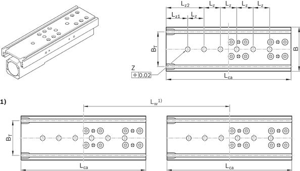
| 1) | 2 carriages (optional) |
| 2) | Centerline-to-centerline distance specified according to customer design. Centerline-to-centerline distance freely selectable between minimum and maximum distance in millimeter increments. |
Dimensions
| Size | MKK-080 | |||||||||||||
| Version | without IMS | with IMS | variable centerline-to-centerline distance | |||||||||||
| Number of carriages | 1 | 1 | 1 | 1 | 1 | 1 | 1 | 1 | 2 | 2 | 2 | 2 | ||
| Lca | without IMS | mm | 260 | 260 1) | 260 | |||||||||
| with IMS | mm | - | 360 2) 3) | - | ||||||||||
| LW | min | mm | - | 320 4) | ||||||||||
| max | mm | - | 960 4) | |||||||||||
| d0 x P | mm | 20 x 5 | 20 x 10 | 20 x 20 | 20 x 40 | 20 x 5 | 20 x 10 | 20 x 20 | 20 x 40 | 20 x 5 | 20 x 10 | 20 x 20 | 20 x 40 | |
| B | mm | 78 | ||||||||||||
| BG | mm | 60 | ||||||||||||
| BT | mm | 60 | ||||||||||||
| G | mm | 70 | ||||||||||||
| G1 | mm | 25 | ||||||||||||
| Lz | mm | 40 | ||||||||||||
| MG | M8 ‒ 10 mm deep | |||||||||||||
| ØZ | H7 | 9 ‒ 2.1 mm deep | ||||||||||||
| 1) | Note: For the length calculation when using IMS, use value Lca with IMS. |
| 2) | Value for length calculation |
| 3) | Clamping surface corresponds to Lca (without IMS) |
| 4) | Centerline-to-centerline distance specified according to customer design. Centerline-to-centerline distance freely selectable between minimum and maximum distance in millimeter increments. |
Carriage with threads and IMS

| 1) | Non-usable clamping surface |
Dimensions
| Size | MKK-080 | |||||||||||||
| Version | without IMS | with IMS | variable centerline-to-centerline distance | |||||||||||
| Number of carriages | 1 | 2 | ||||||||||||
| Lca | without IMS | mm | 260 | 260 1) | 260 | |||||||||
| with IMS | mm | - | 360 2) 3) | - | ||||||||||
| LW | min | mm | - | 320 4) | ||||||||||
| max | mm | - | 960 4) | |||||||||||
| d0 x P | mm | 20 x 5 | 20 x 10 | 20 x 20 | 20 x 40 | 20 x 5 | 20 x 10 | 20 x 20 | 20 x 40 | 20 x 5 | 20 x 10 | 20 x 20 | 20 x 40 | |
| B | mm | 78 | ||||||||||||
| BG | mm | 60 | ||||||||||||
| BT | mm | 60 | ||||||||||||
| G | mm | 70 | ||||||||||||
| G1 | mm | 25 | ||||||||||||
| Lz | mm | 40 | ||||||||||||
| MG | M8 ‒ 10 mm deep | |||||||||||||
| ØZ | H7 | 9 ‒ 2.1 mm deep | ||||||||||||
| 1) | Note: For the length calculation when using IMS, use value Lca with IMS. |
| 2) | Value for length calculation |
| 3) | Clamping surface corresponds to Lca (without IMS) |
| 4) | Centerline-to-centerline distance specified according to customer design. Centerline-to-centerline distance freely selectable between minimum and maximum distance in millimeter increments. |
Carriage with T-slots and IMS

| 1) | Non-usable clamping surface |
Dimensions
| Size | MKK-080 | |||||||||||||
| Version | without IMS | with IMS | variable centerline-to-centerline distance | |||||||||||
| Number of carriages | 1 | 1 | 1 | 1 | 1 | 1 | 1 | 1 | 2 | 2 | 2 | 2 | ||
| Lca | without IMS | mm | 260 | 260 1) | 260 | |||||||||
| with IMS | mm | - | 360 2) 3) | - | ||||||||||
| LW | min | mm | - | 320 4) | ||||||||||
| max | mm | - | 960 4) | |||||||||||
| d0 x P | mm | 20 x 5 | 20 x 10 | 20 x 20 | 20 x 40 | 20 x 5 | 20 x 10 | 20 x 20 | 20 x 40 | 20 x 5 | 20 x 10 | 20 x 20 | 20 x 40 | |
| B | mm | 78 | ||||||||||||
| BG | mm | 60 | ||||||||||||
| BT | mm | 60 | ||||||||||||
| G | mm | 70 | ||||||||||||
| G1 | mm | 25 | ||||||||||||
| Lz | mm | 40 | ||||||||||||
| MG | M8 ‒ 10 mm deep | |||||||||||||
| ØZ | H7 | 9 ‒ 2.1 mm deep | ||||||||||||
| 1) | Note: For the length calculation when using IMS, use value Lca with IMS. |
| 2) | Value for length calculation |
| 3) | Clamping surface corresponds to Lca (without IMS) |
| 4) | Centerline-to-centerline distance specified according to customer design. Centerline-to-centerline distance freely selectable between minimum and maximum distance in millimeter increments. |
T-nuts
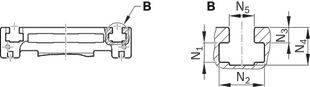
Dimensions
| Size | MKK-080 | |
| Sliding block | DIN557–M5 | |
| N1 | mm | 5 |
| N2 | mm | 9 |
| N3 | mm | 2.5 |
| N4 | mm | 8.5 |
| N5 | mm | 5.2 |
IMS connector

Dimensions
| Size | MKK-080 | |
| BIMS | mm | 126 |
| HIMS | mm | 6.5 |
Project planning information
Calculation example MKK with timing belt side drive
Calculation
Mounting
load errorCommissioning
load errorMaintenance
load errorDelivery notes
load errorSafety Instructions
load errorMotor attachment
load errorMeasurement and test reports
load errorDownloads
 | Declaration of Incorporation for single axis Linear Motion Systems Certificate | R320103141 | 2020-06-01 | All languages | PDF | 409k Product Groups: Linear axes and electromechanical cylinders |
| Safety Instructions for Linear Motion Systems Manual | R320103152_en | 2015-01-01 | English | PDF | 593k Product Groups: Linear axes and electromechanical cylinders |
| Linear Modules MKK/MKR/MLR -040/-065/-080/-110/-140/-145-NN-3/-165-NN-2 Manual | R320103169_EN | 2021-11-01 | English | PDF | 6.9MB Product Groups: Linear Modules only available as PDF |
| Linear Modules MKK / MKR / MLR Catalog | R999000496 | 2021-03-01 | English | PDF | 17.5MB Product Groups: Linear Modules |

Нет отзывов об этом товаре.