
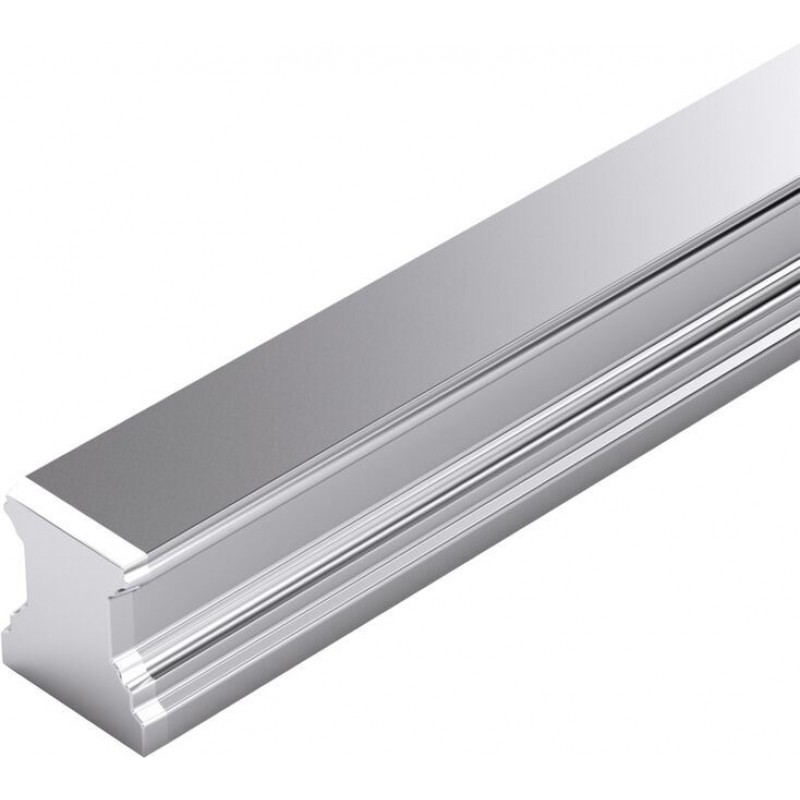
Артикул: RX8709
Ball Guide Rails SNS NR II for mounting from below R2047 .0. ..
Доступно к заказу
Цена по запросу
И выбери подходящего.
Description
- High torque capacity
- Top rigidity in all load directions
- All metal parts are made from corrosion-resistant steel
- Best sealing action of end seals
- Greater side loads permitted
- For mounting from below
- Ball Guide Rail as well as all steel parts made of corrosion-resistant steel according to DIN EN 10088
- Observe the notes for mounting! Please request the "Mounting instructions for Ball Rail Systems" and "Mounting instructions for cover strip".
Features
- Top rigidity in all load directions
- High torque capacity
- No extra space needed at rail ends
Product description
Ball rails can be cut to the length required by the customer.
The maximum lengths for one-piece guide rails can be found in the "Technical data" chapter.
If longer rails are required, Bosch Rexroth supplies them as composite ball guide rails.
Corrosion resistance and conditions of use
Ball Guide Rails Resist NR II as well as all steel parts are made of corrosion-resistant steel as per DIN EN 10088, strip clamps are made of aluminum. Ball Guide Rails Resist NR II are especially suited for use in wet environments, heavily diluted acids, alkali or saline solutions. These linear guides are ideally suited for use at relative humidities above 70% and temperatures exceeding 30°C. Such conditions are mainly found in cleaning plants, electroplating and pickling plants, steam degreasing plants, and also refrigeration machines. Since additional corrosion protection is not required, Ball Rail Systems Resist NR II are especially suitable for use in clean rooms and printed circuit board production in general. Other possible areas of application include the pharmaceutical and food industries.
Ball guide rail with temperature control
Product description of Ball Rail Systems
Selection of a linear guide acc. to DIN 637
Technical data
General technical data
| Size | 15 | 20 | 25 | 30 | 35 | |
| m | kg/m | 1.4 | 2.4 | 3.2 | 5 | 6.8 |
| Lmax | mm | 1856 | 3836 | |||
| Material | NRII | |||||
| Operating conditions | ||||||
| Size | 15 | 20 | 25 | 30 | 35 | |
| Permissible ambient temperature (min ... max) 1) | 0 °C ... +80 °C | |||||
| 1) | Up to 100 °C permissible for short periods. For operation at negative temperatures, please consult us. |
Legend
| Symbol | Description | Unit |
| Lmax | Maximum length | mm |
| m | Mass per meter | kg/m |
Accuracy classes
Dimensions

Dimensions
| Size | 15 | 20 | 25 | 30 | 35 | |
| A2 | mm | 15 | 20 | 23 | 28 | 34 |
| H2 | mm | 16.2 | 20.55 | 24.25 | 28.35 | 31.85 |
| N7 | mm | 7.5 | 9 | 12 | 15 | |
| S7 | mm | M5 | M6 | M8 | ||
| T | mm | 60 | 80 | |||
| T1 min | mm | 10 | 12 | |||
| T1 s | mm | 28 1) | 38 1) | |||
| T1 max | mm | 50 | 68 | |||
| nB | 30 | 64 | 48 | |||
| 1) | Preferred dimension T1S Recommended with tolerances ± 0.75. |
Legend
| Symbol | Description | Unit |
| T1 min | Minimum distance | mm |
| T1 max | Maximum distance | mm |
| T1 s | Preferred dimension | mm |
| T | Spacing of guide rail | mm |
| nB | Maximum number of holes |
Project planning information
See the section on Ball Runner Blocks Resist NR II for the recommended Ball Runner Blocks for the Ball Guide Rails Resist NR II
Combinations of different accuracy classes
Combining Ball Guide Rails and Ball Runner Blocks of different accuracy classes results in different tolerances for the dimensions H and A3 (see "Accuracy classes and their tolerances").
Mounting
Notes for mounting
▶ Composite Ball Guide Rail also available.
General mounting instructions
Accessories
Hydraulic clamping and braking units KBH, FLS
R1619 .40 21
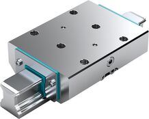
Hydraulic clamping and braking units KBH, FLS
R1619 .40 21
- Very high axial holding forces
- Dynamic and static stabilization in the axial direction
- Heavy-duty brake
- Compact design, compatible with DIN 645
- Clamps and brakes with pressure
Hydraulic clamping and braking units KBH, SLS
R1619 640 20
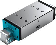
Hydraulic clamping and braking units KBH, SLS
R1619 640 20
- Very high axial holding forces
- Dynamic and static stabilization in the axial direction
- Heavy-duty brake
- Compact design, compatible with DIN 645
- Clamps and brakes with pressure
Hydraulic clamping units KWH, FLS
R1619 .42 11
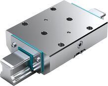
Hydraulic clamping units KWH, FLS
R1619 .42 11
- Very high axial holding forces
- Dynamic and static stabilization in the axial direction
- Compact design, compatible with DIN 645
- Clamps with pressure
Hydraulic clamping units KWH, SLS
R1619 .42 51
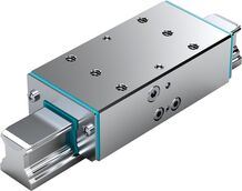
Hydraulic clamping units KWH, SLS
R1619 .42 51
- Very high axial holding forces
- Dynamic and static stabilization in the axial direction
- Compact design, compatible with DIN 645
- Clamps and brakes with pressure
Hydraulic clamping units KWH, SLH
R1619 .42 31
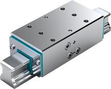
Hydraulic clamping units KWH, SLH
R1619 .42 31
- Very high axial holding forces
- Dynamic and static stabilization in the axial direction
- Compact design, compatible with DIN 645
- Clamps with pressure
Pneumatic clamping and braking units MBPS
R1619 .40 31
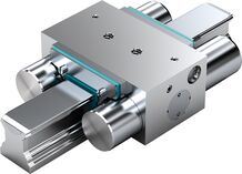
Pneumatic clamping and braking units MBPS
R1619 .40 31
- Clamps and brakes with spring energy accumulator
- Positive locking integrated contact profiles ensure maximum axial and horizontal rigidity, and thus an excellent braking effect
- Dynamic and static stabilization in the axial direction
- Clamps and brakes without pressurization (spring energy)
- Clamping and braking units in short format
Pneumatic clamping and braking units UBPS
R1619 .40 51
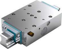
Pneumatic clamping and braking units UBPS
R1619 .40 51
- Clamps and brakes with spring energy accumulator
- Positive locking integrated contact profiles ensure maximum axial and horizontal rigidity, and thus an excellent braking effect
- Dynamic and static stabilization in the axial direction
- Clamps and brakes without pressurization (spring energy)
- Compact design, compatible with DIN 645
Pneumatic clamping units MK
R1619 .42 6.
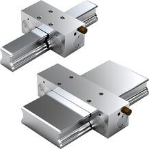
Pneumatic clamping units MK
R1619 .42 6.
- High axial holding forces with short format
- Dynamic and static stabilization in the axial direction
- Simple mechanical gripping principle in LCP and LCPS with good price/performance ratio
- Easy mounting
- Clamps with pressure (pneumatic) The clamping profiles are pressed by compressed air via a dual acting gate valve gear mechanism.
Pneumatic clamping units MKS
R1619 .40 6.
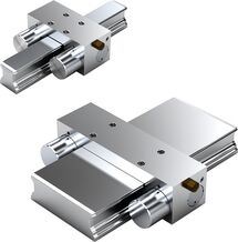
Pneumatic clamping units MKS
R1619 .40 6.
- High axial holding forces with short format
- Dynamic and static stabilization in the axial direction
- Simple mechanical gripping principle in LCP and LCPS with good price/performance ratio
- Easy mounting
- Clamps without pressurization (spring energy). In the event of a pressure drop, it clamps via the dual-action gate valve gear mechanism with two spring assemblies.
Pneumatic clamping units LCP
R1619 242 74
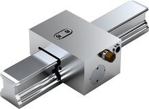
Pneumatic clamping units LCP
R1619 242 74
- High axial holding forces with short format
- Dynamic and static stabilization in the axial direction
- Simple mechanical gripping principle in LCP and LCPS with good price/performance ratio
- Easy mounting
- Clamps with pressure (pneumatic) by means of mechanical gripping
Pneumatic clamping units LCPS
R1619 240 70
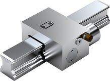
Pneumatic clamping units LCPS
R1619 240 70
- High axial holding forces with short format
- Dynamic and static stabilization in the axial direction
- Simple mechanical gripping principle in LCP and LCPS with good price/performance ratio
- Easy mounting
- Clamps without pressurization (with spring energy) by means of mechanical gripping with a spring assembly (spring energy accumulator)
Manual clamping units HK
R1619 .42 82
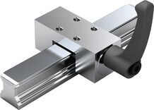
Manual clamping units HK
R1619 .42 82
- Simple and safe design in compact format
- Manually operated clamping unit without auxiliary power
- Freely adjustable hand lever
- Exact positioning, high dynamics, powerful drive and long service life through the use of high-precision linear screw drives
- Manual clamping unit
Standard loose cover strip with snap fit

Standard loose cover strip with snap fit
- The cover strip is easy to clip on and remove, thereby considerably simplifying and speeding up assembly.
- No need to plug every single hole.
- No time delay while waiting for adhesive to harden when using adhesive tape.
- Can be mounted and removed several times (up to four times).
- For initial installation, storage and replacement
Loose cover strip with sliding fit

Loose cover strip with sliding fit
- The cover strip is easy to clip on and remove, thereby considerably simplifying and speeding up assembly.
- No need to plug every single hole.
- No time delay while waiting for adhesive to harden when using adhesive tape.
- Can be mounted and removed several times (up to four times).
- For initial installation, storage and replacement
Expanding tool
for Ball Rail Systems

Expanding tool
for Ball Rail Systems
- For creating a sliding fit in the cover strip
Cover strip mounting kit
for Ball Rail Systems

Cover strip mounting kit
for Ball Rail Systems
- Mounting aid and lift-off plate
Protective caps for Ball Rail Systems
R1619 .39 00

Protective caps for Ball Rail Systems
R1619 .39 00
- For ball guide rails with threaded holes at the end faces
- Plastic protective cap, black
- Screws made of corrosion-resistant steel as per DIN EN 10088
- Washer made of galvanized steel
Strip clamps for Ball Rail Systems
R1619 .39 .0

Strip clamps for Ball Rail Systems
R1619 .39 .0
- For ball guide rails without threaded holes at the end faces
- Aluminum strip clamps (anodized)
- Clamping screws and nuts made of corrosion-resistant steel as per DIN EN 10088
Plastic mounting hole plugs for Ball Rail Systems
R1605 .0

Plastic mounting hole plugs for Ball Rail Systems
R1605 .0
Steel caps for Ball Rail Systems
R1606 75

Steel caps for Ball Rail Systems
R1606 75
Mounting tool for steel caps

Mounting tool for steel caps
- Two-piece, with mounting instructions
- The two-piece mounting tool is suitable for mounting hole plugs in built-in guide rails (mounting instructions enclosed)
V-guide for lateral retention of Ball Guide Rails

V-guide for lateral retention of Ball Guide Rails
- Mounting aid for lateral retention of ball guide rails
- Material: Steel
- Design: black finish
Certification
Directives and standards
Safety Instructions
Notes
Ordering codes
Material numbers
| Size | Part number 1) | CAD data | Buy | Rail length 4) | Accuracy class | Number of sections |
| 15 | R204710431 2) | L = nB • T ‒ 4 mm | N | One-piece | ||
| R204710432 3) | L = nB • T ‒ 4 mm | N | Composite | |||
| R204710331 2) | L = nB • T ‒ 4 mm | H | One-piece | |||
| R204710332 3) | L = nB • T ‒ 4 mm | H | Composite | |||
| R204710231 2) | L = nB • T ‒ 4 mm | P | One-piece | |||
| R204710232 3) | L = nB • T ‒ 4 mm | P | Composite | |||
| 20 | R204780431 2) | L = nB • T ‒ 4 mm | N | One-piece | ||
| R204780432 3) | L = nB • T ‒ 4 mm | N | Composite | |||
| R204780331 2) | L = nB • T ‒ 4 mm | H | One-piece | |||
| R204780332 3) | L = nB • T ‒ 4 mm | H | Composite | |||
| R204780231 2) | L = nB • T ‒ 4 mm | P | One-piece | |||
| R204780232 3) | L = nB • T ‒ 4 mm | P | Composite | |||
| 25 | R204720431 2) | L = nB • T ‒ 4 mm | N | One-piece | ||
| R204720432 3) | L = nB • T ‒ 4 mm | N | Composite | |||
| R204720331 2) | L = nB • T ‒ 4 mm | H | One-piece | |||
| R204720332 3) | L = nB • T ‒ 4 mm | H | Composite | |||
| R204720231 2) | L = nB • T ‒ 4 mm | P | One-piece | |||
| R204720232 3) | L = nB • T ‒ 4 mm | P | Composite | |||
| 30 | R204770431 2) | L = nB • T ‒ 4 mm | N | One-piece | ||
| R204770432 3) | L = nB • T ‒ 4 mm | N | Composite | |||
| R204770331 2) | L = nB • T ‒ 4 mm | H | One-piece | |||
| R204770332 3) | L = nB • T ‒ 4 mm | H | Composite | |||
| R204770231 2) | L = nB • T ‒ 4 mm | P | One-piece | |||
| R204770232 3) | L = nB • T ‒ 4 mm | P | Composite | |||
| 35 | R204730431 2) | L = nB • T ‒ 4 mm | N | One-piece | ||
| R204730432 3) | L = nB • T ‒ 4 mm | N | Composite | |||
| R204730331 2) | L = nB • T ‒ 4 mm | H | One-piece | |||
| R204730332 3) | L = nB • T ‒ 4 mm | H | Composite | |||
| R204730231 2) | L = nB • T ‒ 4 mm | P | One-piece | |||
| R204730232 3) | L = nB • T ‒ 4 mm | P | Composite |
| 1) | Please configure the product to place it in the shopping cart. |
| 2) | Rail length up to Lmax |
| 3) | Rail length greater than Lmax. The end number changes depending on the number of sections. 2 is preset here as an example. |
| 4) | Recommended rail length, other lengths possible. |
| Ordering example 1 (up to Lmax) | Ordering example 2 (beyond Lmax) |
| Options: | Options: |
| Ball Guide Rail NR II, SNS | Ball Guide Rail NR II, SNS |
| Size 30 | Size 30 |
| Accuracy class H | Accuracy class H |
| One-piece | 2 sections |
| Rail length L = 1676 mm | Rail length L = 5116 mm |
| Material number: | Material number: |
| R2047 703 31, 1676 mm | R2047 703 32, 5116 mm |
Legend
| Symbol | Description | Unit |
| L | Rail length | mm |
| nB | Maximum number of holes | |
| T | Spacing of guide rail | mm |
Ordering guide rails in the recommended rail lengths
Downloads
 | Profiled rail systems Manual | R320103885_EN | 2016-09-01 | English | PDF | 11.5MB Product Groups: Linear guides |
| Catalog BSHP Ball Rail Systems Catalog | R999000485 | 2020-10-01 | English | PDF | 15MB Product Groups: Ball Rail Systems only available as PDF |

Нет отзывов об этом товаре.