
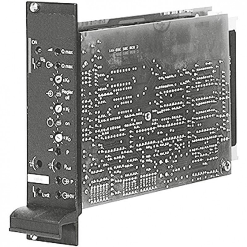
Доступно к заказу
Цена по запросу
И выбери подходящего.
Description
- Component series 2X
Features
- Suitable for controlling direct and pilot-operated high-response valves
- Amplifier with additional electronics (daughter card)
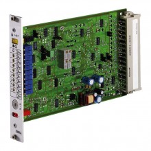
- Analog amplifiers in Europe format for installation in 19" racks
- Valve position control with PID behavior
- Pressure control with external pressure load cell
- Controlled output stage
- Enable input
- Short-circuit-proof outputs
- Adjustment options: Valve zero point
- Cable break detection for actual value cable and pressure sensor
- Fast energization and fast deletion for short actuating times
- External controller shut-off
- Suitable for pressure sensors (1...6 V, 0...10 V, 4...20 mA), see data sheet 30271
Product description
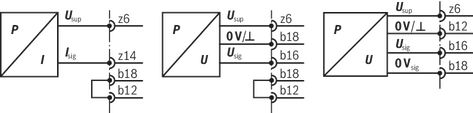
Pressure sensor connection versions
Type code
| 01 | 02 | 03 | 04 | 05 | 06 | 07 | 08 | 09 | 10 | 11 | ||||
| VT- | V | A | R | A | P | 1 | – | – | 2X | / | V0 | / |
| 01 | VT- | |
| 02 | V | |
| Hydraulic component (control) | ||
| 03 | Axis control | A |
| Valve type | ||
| 04 | High-response valve | R |
| Control | ||
| 05 | Analog | A |
| Function | ||
| 06 | p/Q control | P |
| Output stages | ||
| 07 | 1 output stage | 1 |
| Serial number for types | ||
| 08 | 2.7 A solenoid | 527 |
| 3.7 A solenoid | 537 | |
| 09 | Component series 20 ... 29 (20 ... 29: unchanged technical data and pin assignment) | 2X |
| Customer version | ||
| 10 | Catalog version | V0 |
| Option | ||
| 11 | High-response valve size 6/10, direct operated | no code |
| p/Q valve size 10, direct operated | 5/3V | |
| High-response valve, pilot-operated | 2STV | |
| High-response valve, pilot-operated, control line A → X | 3/2V | |
Technical data
General
| Type / version | VT-VARAP1-527 | VT-VARAP1-537 | |||
| Supply voltage | nominal 24 V= battery voltage 21...40 V, rectified alternating voltage Ueff = 21...28 V (single-phase, full-wave rectifier) | ||||
| Smoothing capacitor, separately | Recommendation: Capacitor module VT 11110 (see data sheet 30750) (only necessary if the ripple of UB >10 %) | ||||
| Valve solenoid, max. | A | 2.7 | 3.7 | ||
| Current consumption, max. 1) | A | 1.7 | 2.7 | ||
| Power consumption (typical) | W | 37 | 55 | ||
| Input signal (command value) | b20: 0...±10 V – differential amplifier z20: 0...±10 V – differential amplifier (Ri= 100 kΩ) | ||||
| Input signal (command value p) | z12: 0...+10 V – differential amplifier z10: 0 V – differential amplifier | ||||
| Actual value from the pressure sensor | z14: 4...20 mA – current input b16: 0...+10 V/1...+6 V – voltage input b18: 0 V – reference | ||||
| Pressure controller OFF | b10: 6...40 V= | ||||
| External enquiry pressure controller active | z24: 24 V/0.1 A max. | ||||
| Limit frequency | for applications ≤ 30 Hz | ||||
| Signal source | Potentiometer 10 kΩ Supply with ±10 V from b32, z32 (10 mA) or external signal source | ||||
| Enable output stage | at z16, U= 8.5...40 V, Ri = 100 kΩ LED (green) on front plate lights up | ||||
| Sensor supply | z6: +15 V/35 mA, Ri ~ 25 Ω | ||||
| Position transducer | Supply | b30: -15 V (25 mA) z30: +15 V (35 mA) | |||
| Pilot control valve | Actual value signal | b22: 0...±10 V, RL = 10 kΩ/Ref. b24 | |||
| Main stage | Actual value reference | b26: 0...±10 V, RL = 10 kΩ/Ref. b28 | |||
| Solenoid output | Clocked current controller | ||||
| Imax | A | 2.7 | 3.7 | ||
| Cable lengths between amplifier and valve | Solenoid cable | m | 20 | ||
| m | 20 … 60 | ||||
| Number of wires / line cross-section | Position transducer | 4 x 0.5 mm2 (shielded) | |||
| Pressure sensor | 4 x 0.5 mm2 (shielded) | ||||
| Special features | Cable break protection for actual value cable Position control with PID behavior Pulsed output stage Fast energization and fast deletion for short actuating times Short-circuit-proof outputs External controller shut-off | ||||
| Adjustment | Zero point via trimming potentiometer ±5 % Command value attenuator Q Pressure controller KP, KI and KD Sensitivity pressure load cell Zero point pressure load cell | ||||
| LED displays | green | Enable | |||
| yellow | Cable break position transducer | ||||
| red | Supply voltage (UB too low) | ||||
| yellow | Pressure controller OFF | ||||
| yellow | Pressure controller working | ||||
| both yellow LEDs are flashing | Cable break pressure sensor | ||||
| Error message | Cable break actual value | z22: Open collector output to +UB max. 100 mA; no error: +UB | |||
| Plug-in connection | Plug to DIN 41612-F32 | ||||
| Operating temperature | °C | 0 … +70 | |||
| Storage temperature range | °C | -20 … +70 | |||
| Weight | m | kg | 0.49 | ||
| 1) | Current consumption may increase with min. UB and extreme cable lengths to the control solenoid |
Power zero b2 and control zero b12 or b14 or z28 must be separately led to the central ground (neutral point).
(For applications outside these values, please consult us!)
Diagrams/characteristic curves
a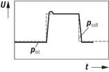 | ||
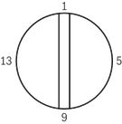
b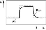 | Problem: P share too small Solution: → Rotate KP against 13 (fine adjustment) → P gain >
| |
| DIL 14 | ON | |
| DIL 15 | OFF | |
| DIL 16 | ON | |
c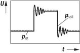 | Problem: P share too large Solution: → Rotate KP against 0 (fine adjustment) ➝ Use DIL 14–16 to reduce the P gain according to the table | |
d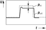 | Problem: P share correct, control deviation too large Solution: ➝ Increase the I gain share → DIL 11 ON = I share = 0 DIL 12 ON = I share connected → Rotate KI against 13 | |
e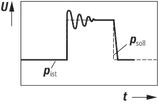 | Problem: Time constant of the I share too low Solution: ➝ Rotate KI against 13 until control deviation and vibration are perfect → If KI = 13 is not sufficient, the P share must also be reduced | |
f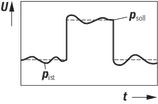 | Problem: D share too low Solution: ➝ Rotate KD against 13 → D share > | |
| DIL 8 | ON | |
| DIL 9 | OFF | |
| DIL 10 | OFF | |
Electrical connection
Front plate
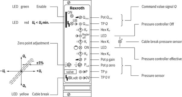
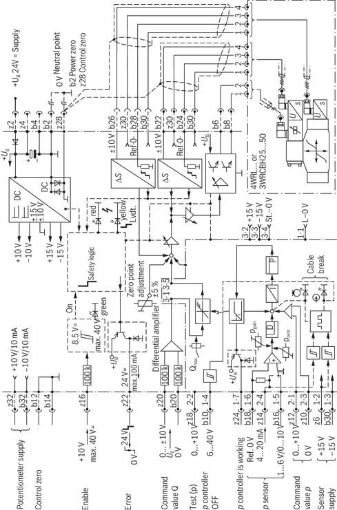
Block diagram with pin assignment
0811405152, 0811405153, 0811405154

Block diagram with pin assignment
0811405155, 0811405156
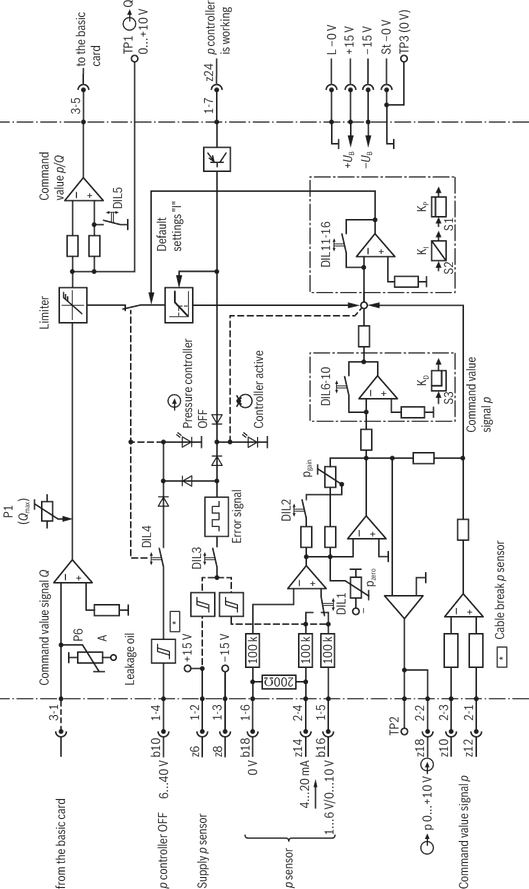
Block diagram daughter card
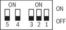
Mode setting (DIL switch, daughter card)

DIL switch
HEXCODE switch
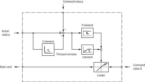
Principle of the control loop
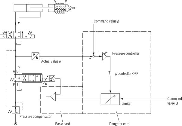
Example 2
Flow with load compensation controlled via pressure compensator and the pressure regulated in the closed control loop (pressure cut off).
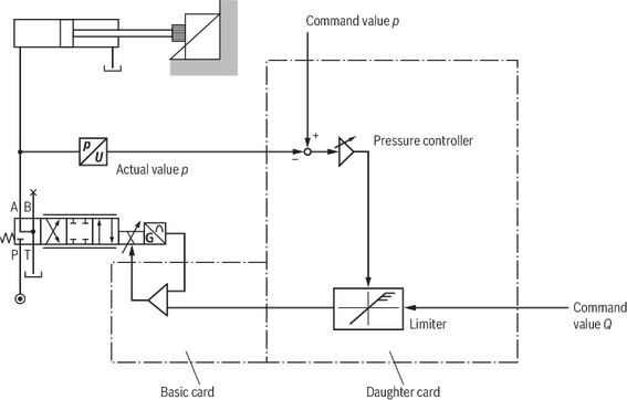
Example 1
Pressure control in a cylinder chamber for achieving a constant clamping force.
Dimensions
load errorDownloads
 | p/Q 闭环控制放大器 Data Sheet | RC30058 | 2012-06-30 | Chinese | PDF | 1.2MB Product Groups: Axis control VT-VARAP1-...-2X/... |
| p/Q-Regelverstärker Data Sheet | RD30058 | 2012-06-30 | German | PDF | 959k Product Groups: Axis control VT-VARAP1-...-2X/... |
| p/Q closed-loop control amplifier Data Sheet | RE30058 | 2012-06-30 | English | PDF | 942k Product Groups: Axis control VT-VARAP1-...-2X/... |
| Amplificateurs de régulation p/Q Data Sheet | RF30058 | 2012-06-30 | French | PDF | 946k Product Groups: Axis control VT-VARAP1-...-2X/... |
| Amplificador regulador p/Q Data Sheet | RS30058 | 2012-06-30 | Spanish | PDF | 944k Product Groups: Axis control VT-VARAP1-...-2X/... |

Цена по запросу


Цена по запросу
Цена по запросу
Цена по запросу
Нет отзывов об этом товаре.