
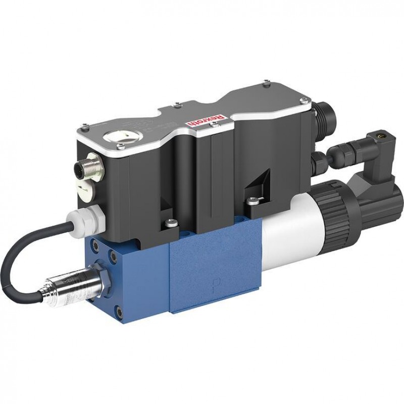
Артикул: RX7032
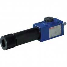
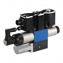
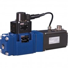
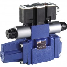
Proportional directional valves, direct operated, with pQ functionality STW 0195, STW 0196
Доступно к заказу
Цена по запросу
И выбери подходящего.
Description
- Size 6, 10
- Component series 2X, 1X
Features
- 3-way proportional directional valves with integrated digital control electronics IAC-P
- Completely adjusted unit consisting of position-controlled valve, pressure sensor and field bus connection
- Operation by means of proportional solenoids with central thread and detachable coil
- Valve control spool, position-controlled
- Integrated pressure sensor plate (optional)
- Porting pattern according to ISO 4401
- Analog interface for command and actual value
- Design for CAN bus with CANopen protocol DS 408 or Profibus-DP
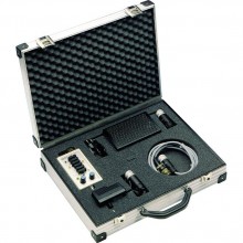
- Quick commissioning via PC and commissioning software WIN-PED
Product description
Set-up
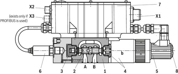
The IAC-P valve basically consists of:
- Housing (1) with connection surface
- Control spool (2) with compression spring (3)
- Solenoid and pole tube (4) with central thread
- Position transducer (5)
- Pressure sensor (6)
- Integrated digital control electronics IAC-P (7) with bus connection (X2) and central connector (X1).
- If solenoids (4) are not operated, spool position A → T (with version "0196-1X/1" additionally B → T)
- Functions:
- Flow control (Q)
- Pressure control (p)
- Substitutional control p/Q
- The command value presetting can alternatively be specified via an analog interface (X1) or via the field bus interface (X2, X3).
- The actual value signals are provided via an analog interface (X1) and can additionally be read out via the field bus (X2, X3).
- The controller parameters are set via the field bus (X2, X3).
- Separate supply voltage for bus/controller and power part (output stage) for safety reasons
- Cable break of pressure sensor supply line (6)
- Undervoltage
- Cable break position transducer (5)
- Communication error
- Watchdog
- Cable break of command value inputs
- Pressure ramp
- Internal command value profile
- Enable function analog / digital
- Error output 24 V
- Parameterization
- Diagnosis
- Comfortable data management on a PC
- PC operating systems: Windows 2000 or Windows XP
Functional description
The digital integrated control electronics enables the following error detection (diagnosis):
The following additional functions are available:
WINPED PC program
To implement the project planning task and to parameterize the IAC-P valves, the user may use the WINPED commissioning software (see accessories):
| Qsoll | Q-Steuerung | p-Regelung |
| < 12 mA | A → T | inactive |
| > 12 mA | Substitutional closed-loop control: (A → T or P → A) | |
Notice!
Due to the design principle, internal leakage is inherent to the valves, which may increase over the life cycle. The tank line must not be allowed to run empty. With corresponding installation conditions, a preload valve must be installed.
Important notice:
The PG fitting (11) must not be opened. Mechanical adjustment of the adjustment nut located below is prohibited and damages the valve!
Type code
| 01 | 02 | 03 | 04 | 05 | 06 | 07 | 08 | 09 | 10 | ||||
| STW | ‒ | / | V | ‒ | 24 | ‒ | * |
| 01 | 3-way proportional directional valves with integrated digital control electronics IAC-P | STW |
| 02 | Size 6 | 0195 |
| Size 10 | 0196 | |
| 03 | STW0196 Component series 10 ... 19 (10 ... 19: unchanged installation and connection dimensions) - Size 10 | 1X |
| STW0195 Component series 20 ... 29 (20 ... 29: unchanged installation and connection dimensions) - Size 6 | 2X | |
| Rated flow NG6 (version "0195") | ||
| 04 | P → A: 10 l/min; A → T: 20 l/min | 1 |
| P → A: 20 l/min; A → T: 20 l/min | 2 | |
| Rated flow NG10 (version "0196") | ||
| 04 | P → A: 65 l/min; A → T: 60 l/min; B → T: 60 l/min | 1 |
| Seal material | ||
| 05 | FKM seals | V |
| Pressure rating of the integrated pressure sensor | ||
| 06 | 50 bar | 3 |
| 160 bar | 5 | |
| 250 bar | 8 | |
| 07 | Supply voltage 24 V | 24 |
| Bus interface | ||
| 08 | CANBus DS - 408 | C |
| Profibus DP V0/V1 | P | |
| Electrical interface | ||
| 09 | Command value ±10 V | A6 |
| Command value 4 to 20 mA | F6
| |
| 10 | Further details in the plain text | * |
Technical data
general
| Type | STW 0195 | STW 0196 | |
| Size | 6 | 10 | |
| Installation position | any, preferably horizontal | ||
| Ambient temperature range | °C | -20 … +50 | |
| Storage temperature range | °C | -20 … +80 | |
| Weight | kg | 2.4 | 6.5 |
hydraulic
| Size | 6 | 10 | |||
| Maximum operating pressure | Port P (sensor 50 bar) | bar | 50 | ||
| Port P (sensor 160 bar) | bar | 160 | |||
| Port P (sensor 250 bar) | bar | 250 | |||
| Port T (sensor 50 bar) | bar | 50 | |||
| Port T (sensor 160 bar) | bar | 160 | |||
| Port T (sensor 250 bar) | bar | 210 | |||
| Port A (sensor 50 bar) | bar | 50 | |||
| Port A (sensor 160 bar) | bar | 160 | |||
| Port A (sensor 250 bar) | bar | 250 | |||
| Port B (sensor 50 bar) | bar | 50 | |||
| Port B (sensor 160 bar) | bar | 160 | |||
| Port B (sensor 250 bar) | bar | 250 | |||
| Nominal flow | P → A | l/min | 65 | ||
| A → T, B → T | l/min | 60 | |||
| Control spool 1 | P → A | l/min | 10 | ||
| A → T | l/min | 20 | |||
| Control spool 2 | P → A | l/min | 20 | ||
| A → T | l/min | 20 | |||
| Maximum flow | See performance limits | ||||
| Hydraulic fluid | see table | ||||
| Hydraulic fluid temperature range | °C | -20 … +80 | |||
| preferably | °C | +40 … +50 | |||
| Viscosity range | mm²/s | 20 … 380 | |||
| preferably | mm²/s | 30 … 46 | |||
| Maximum admissible degree of contamination of the hydraulic fluid, cleanliness class according to ISO 4406 (c) 1) | Class 20/18/15 according to ISO 4406 (c) | ||||
| Hysteresis | % | ≤ 0.1 | |||
| Range of inversion | % | ≤ 0.05 | |||
| Response sensitivity | % | ≤ 0.05 | |||
| Zero shift upon change of | Hydraulic fluid temperature | %/10 K | ≤ 0.15 | ||
| Operating pressure | %/100 bar | ≤ 0.1 | |||
| 1) | The cleanliness classes specified for the components must be adhered to in hydraulic systems. Effective filtration prevents faults and simultaneously increases the life cycle of the components. For the selection of the filters, see www.boschrexroth.com/filter. |
| Hydraulic fluid | Classification | Suitable sealing materials | Standards | |
| Mineral oil | HL, HLP, HLPD, HHVLP, HVLPD | NBR / FKM | DIN 51524 | |
| Bio-degradable | Insoluble in water | HETG | NBR / FKM | ISO 15380 |
| HEES | FKM | |||
| Soluble in water | HEPG | FKM | ISO15380 | |
| Containing water | Water-free | HFDU, HFDR | FKM | ISO 12922 |
| Containing water | HFC (Fuchs Hydrotherm 46M, Petrofer Ultra Safe 620) | NBR | ISO 12922 | |
| Important information on hydraulic fluids: | ||||
| For more information and data on the use of other hydraulic fluids please contact us. There may be limitations regarding the technical valve data (temperature, pressure range, life cycle, maintenance intervals, etc.). The flash point of the process and operating medium used must be 40 K over the maximum solenoid surface temperature. Flame-resistant - containing water: Bio-degradable and flame-resistant – containing water: If this hydraulic fluid is used, small amounts of dissolved zinc may get into the hydraulic system. | ||||
electrical
| Size | 6 | 10 | ||
| Voltage type | Direct voltage | |||
| Maximum current consumption | of the amplifier | A | 2 | |
| of the amplifier (impulse current) | A | 3 | ||
| Maximum current | Output stage | A | 1.7 | |
| Signal part | A | 0.3 | ||
| Actuated time 1) | % | 100 | ||
| Maximum coil temperature 2) | °C | 150 | ||
| Protection class according to DIN EN 60529 | IP65 (If a suitable and a correctly mounted mating connector are used.) | |||
| Power supply | V | 24 | ||
| Supply voltage range | V | 19,4 … 35 | ||
| Admissible residual ripple | Vpp | 2 | ||
| Earthing (GND) | V | 0 | ||
| Enable input range | "A6" | V | 9 … 35 | |
| "F6" | V | 9 … 35 | ||
| Command value input | UQ "A6" | mA | 10 | |
| Command value input range | UP "A6" | mA | 0 … 10 | |
| IQ and IP "F6" | mA | 4 … 20 | ||
| Actual value output | UQ "A6" | V | ± 10 | |
| Actual value output range | UP "A6" | mA | 0 … 10 | |
| IQ and IP "F6" | mA | 4 … 20 | ||
| Control voltage | Level as for pin 1 | |||
| 0 V reference potential | For pins 3, 6, 8 and 11 (connected to pin 2 in valve) | |||
| Error output | 24 V (19.4 V to 35 V), 200 mA maximum load | |||
| 1) | Connect the valve to the supply voltage only when this is required for the functional sequence of the machine. |
| 2) | Due to the surface temperatures occurring at solenoid coils, the European standards ISO 13732-1 and ISO 4413 need to be adhered to. |
Sensor technology
| Overload protection | Sensor 50 bar | bar | 110 |
| Sensor 160 bar | bar | 320 | |
| Sensor 250 bar | bar | 500 | |
| Bursting pressure | Sensor 50 bar | bar | 200 |
| Sensor 160 bar | bar | 640 | |
| Sensor 250 bar | bar | 1000 | |
| Characteristic curve deviation | % | < 0.2 | |
| Hysteresis | % | < 0.1 | |
| Repetition accuracy | % | < 0.05 | |
| Setting time (10 ... 90 %) | ms | < 1 | |
| Long-term drift (1 year) under reference conditions | % | < 0.1 | |
| Conformity | CE according to EMC directive EN 61000-6-2 / EN 61326-2-3 and EN 61000-6-3 / EN 61326-2-3 | ||
Diagrams/characteristic curves
(measured with HLP46, ϑÖl = 40 ±5 °C)
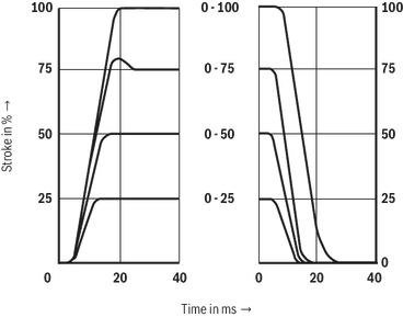
Transition function with stepped electric input signals; A → T
STW0195
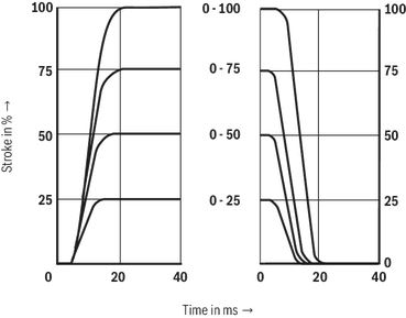
Transition function with stepped electric input signals; P → A
STW0195
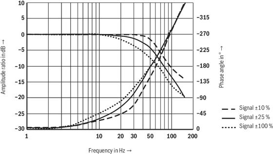
Frequency response
STW0195
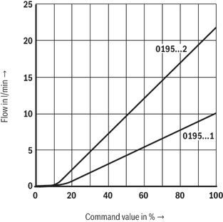
Flow characteristic curve STW0195
(A → T, Δp = 5 bar)

Flow characteristic curve STW0195
(P → A, Δp = 5 bar)
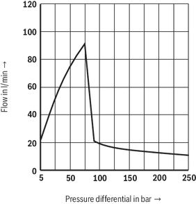
Performance limits STW0195
Position-controlled
P → A 10 l/min, A → T: 20 l/min - A → T)
P → A: 20 l/min, A → T: 20 l/min - A → T)
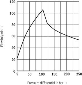
Performance limits STW0195
Position-controlled
P → A 10 l/min, A → T: 20 l/min - P → A)

Performance limits STW0195
Position-controlled
P → A 20 l/min, A → T: 20 l/min - P → A)
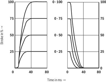
Transition function with stepped electric input signals; A → T, B → T
STW0196
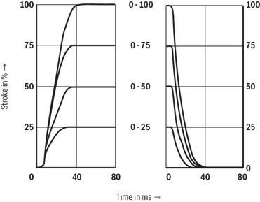
Transition function with stepped electric input signals; P → A
STW0196
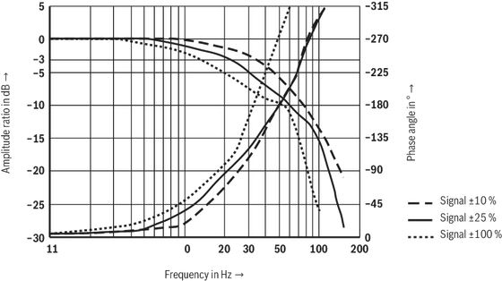
Frequency response
STW0196
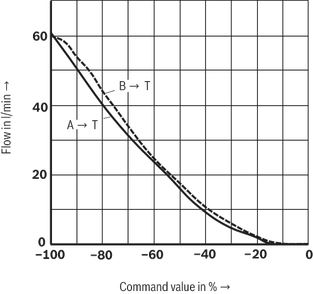
Flow characteristic curve STW0196
(A/B → T, Δp = 5 bar)
Flow characteristic curve STW0196
(P → A, Δp = 5 bar)
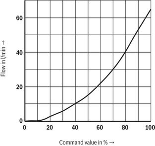
Performance limits STW0196
Position-controlled (A → T)

Performance limits STW0196
Position-controlled (P → A)

Performance limits STW0196
Position-controlled (B → T)
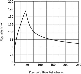
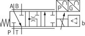
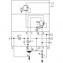
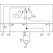
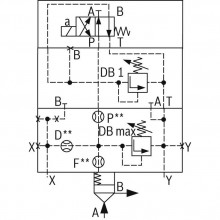
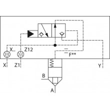
Symbols/Circuit diagrams
STW0195
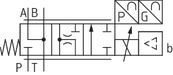
STW0196
Electrical connection
load errorDimensions
load errorProject planning information
load errorDownloads


Цена по запросу
Цена по запросу
Нет отзывов об этом товаре.