
Доступно к заказу
Цена по запросу
И выбери подходящего.
Description
- Size 10
- Component series 6X
- Maximum operating pressure 315 bar
- Maximum flow 120 l/min
Features
load errorProduct description
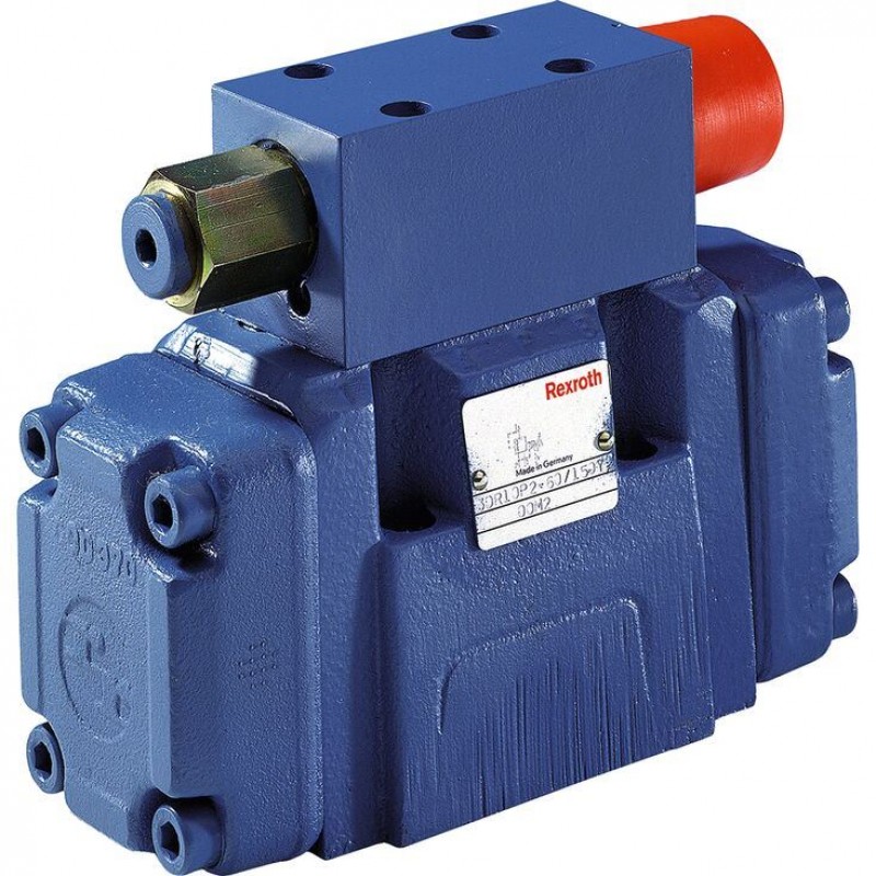
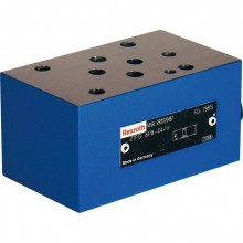
The pressure valve type 3DR is a pilot-operated 3-way pressure reducing valve with pressure limitation of the secondary circuit. It is used to reduce the system pressure.
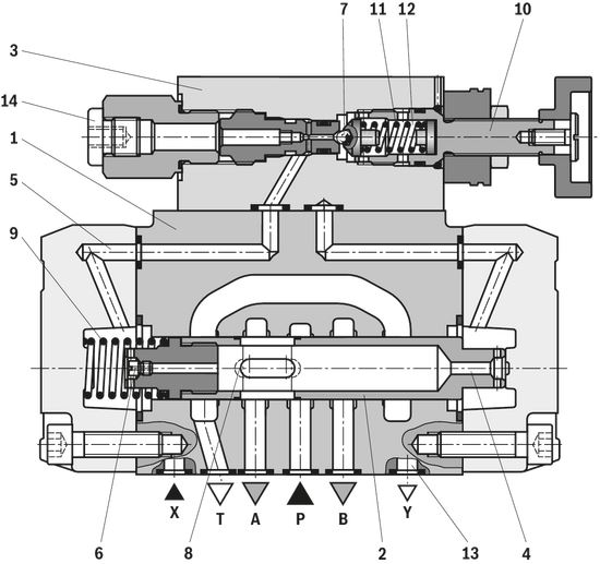
The pressure reducing valve basically consists of the main valve (1) with control spool (2) and pilot control valve (3) with pressure adjustment element (10).
The valve is open in initial position. Hydraulic fluid can flow from channel P to channel A without restrictions. The pressure in channel A is simultaneously applied via the bore (4) at the piston area opposite the compression spring (9). Simultaneously, pressure is applied via the nozzle (6) to the spring-loaded side of the control spool (2) and via channel (5) to
ball (7) in the pilot control valve (3). Depending on the setting of the compression spring (11), pressure builds up upstream of the ball (7) and in channel (5) holding the control spool (2) in open position. Hydraulic fluid flows from channel P via the control spool (2) to channel A until a pressure builds up in channel A exceeding the pressure value set at the compression spring (11) and opening the ball (7).
The control spool (2) moves to closed position. The desired reduced pressure is reached if there is a balance between the pressure in channel A and the pressure value set at the compression spring (11).
If the pressure in channel A increases further due to an external force effect at the actuator, the control spool (2) is pushed further against the compression spring (9). In this way, channel A is connected to channel T via the control edge (8) at the control spool (2). So much hydraulic fluid is discharged into the tank that the pressure can no longer increase. The pilot oil return from the spring chamber (12) is always realized externally via the control line (13) at port Y. A depressurized connection to the tank must always be ensured.
The pressure gauge connection (14) enables control of the reduced pressure in channel A.
Type 3DR 10 P4–6X/…
Type code
| 01 | 02 | 03 | 04 | 05 | 06 | 07 | 08 | 09 | 10 | |||
| 3DR | 10 | P | – | 6X | / | Y | / | 00 | * |
| 01 | 3-way pressure reducing valve | 3DR |
| 02 | Size 10 | 10 |
| 03 | Subplate mounting | P |
| Adjustment element | ||
| 04 | Rotary knob | 4 |
| Sleeve with hexagon and protective cap | 5 | |
| Lockable rotary knob with scale | 6 1) | |
| Rotary knob with scale | 7 | |
| 05 | Series 60 to 69 (60 to 69: unchanged installation and connection dimensions) | 6X |
| 06 | Set pressure up to 50 bar | 50 |
| Set pressure up to 100 bar | 100 | |
| Set pressure up to 200 bar | 200 | |
| Set pressure up to 315 bar | 315 | |
| Pilot oil flow | ||
| 07 | Internal pilot oil supply, external pilot oil return | Y |
| 08 | With stroke limitation | 00 |
| 09 | NBR seals | M |
| FKM seals (other seals upon request) | V | |
| Observe compatibility of seals with hydraulic fluid used. | ||
| 10 | Further details in the plain text | * |
| 1) H-key with material no. 00008158 is included in the scope of delivery. |
Preferred types and standard units are specified in the EPS (standard price list).
Technical data
general
| Size | 10 | |
| Weight | kg | 6 |
| Installation position | any | |
| Direction of flow | see symbol | |
| Ambient temperature range | °C | -30 … +50 |
hydraulic
| Size | 10 | ||
| Nominal pressure | bar | 315 | |
| Maximum operating pressure | Port P | bar | 315 |
| Anschluss A | bar | 315 | |
| Port Y | separate and depressurized to the tank | ||
| Set pressure | Minimum | flow-dependent, see "characteristic curves" | |
| Maximum | bar | 50 100 200 315 | |
| Maximum flow | l/min | 120 | |
| Hydraulic fluid | see table | ||
| Hydraulic fluid temperature range | NBR seals | °C | -30 … +80 |
| FKM seals | °C | -20 … +80 | |
| Viscosity range | mm²/s | 10 … 800 | |
| Maximum admissible degree of contamination of the hydraulic fluid | Class 9 according to NAS 1638. For this, we recommend using a filter with a minimum retention rate of β10 ≥ 75. | ||
| Hydraulic fluid | Classification | Suitable sealing materials | Standards | |
| Mineral oil | HL, HLP | FKM, NBR | DIN 51524 | |
| Bio-degradable | Insoluble in water | HEES (synthetic esters) | FKM | VDMA 24568 |
| HETG (rape seed oil) | FKM, NBR | |||
| Soluble in water | HEPG (polyglycols) | FKM | VDMA 24568 | |
| Other hydraulic fluids on request | ||||
| 1) Suitable for NBR and FKM seals | |
| 2) Suitable for FKM seals only |
(For applications outside these values, please consult us!)
Diagrams/characteristic curves
(measured at v = 41 mm2/s and ϑ = 50 °C)
Outlet pressure pA dependent on the flow qV
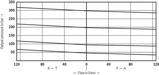
The characteristic curves apply for outlet pressurepT = zero in the entire flow range.
Flow resistance
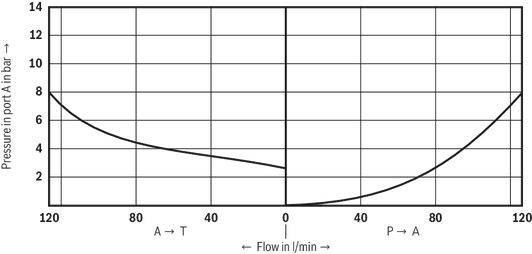
Minimum set pressure pmin dependent on the flow qV
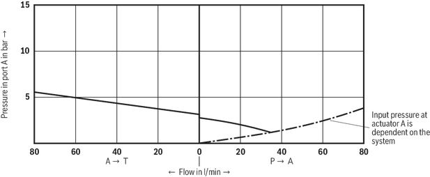
The characteristic curves apply for outlet pressure pT = zero in the entire flow range.
Pilot flow qV st dependent on the flow qV

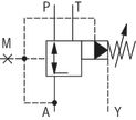
Symbols/Circuit diagrams
Dimensions
load errorDownloads
 | Pressure reducing valve, pilot operated Data Sheet | RE26915 | 1997-10-01 | English | PDF | 86k Product Groups: Pilot operated |

Нет отзывов об этом товаре.