
Доступно к заказу
Цена по запросу
И выбери подходящего.
Description
Product description
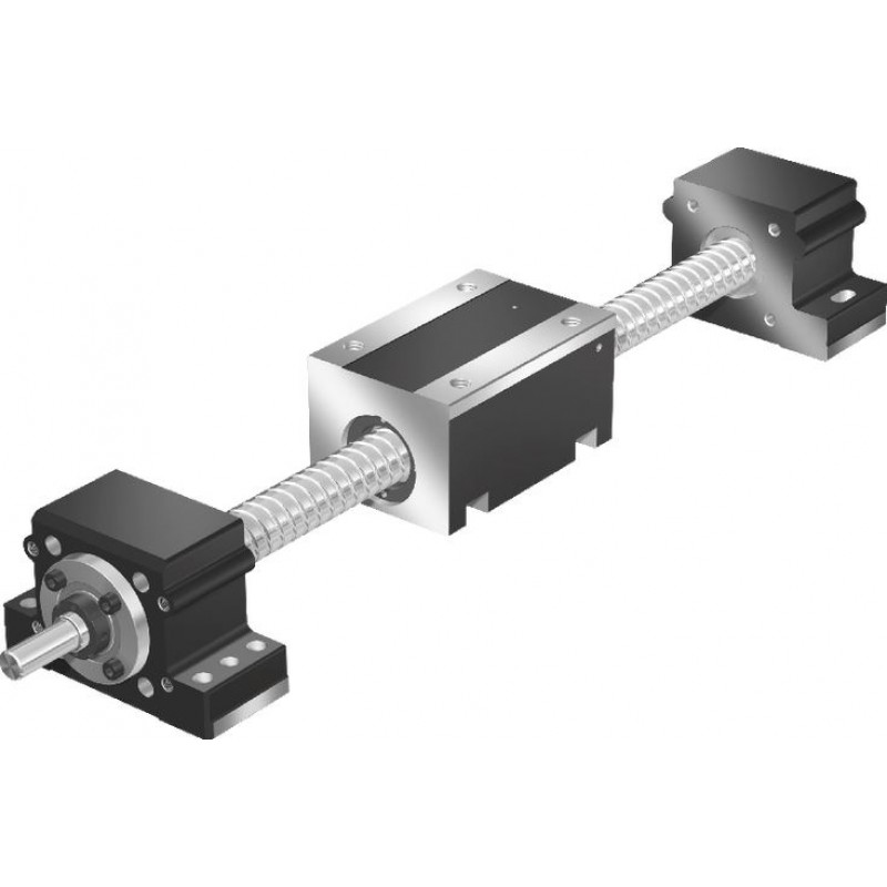
Design

| 1) | With fixed and floating bearing |
| 2) | With fixed bearing only |
1 Rexroth Ball Screw Assembly
2 Pillow block fixed bearing end (drive side)
3 Housing with nut
4 Pillow block floating bearing end
| Nuts | ZEM-E  | FEM-E-S / FEP-E-S  | FEM-E-C  |
| can be combined with1) |  |  |  |
| Nut housing | MGA 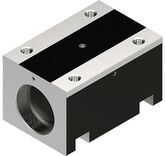 | MGS  | MGD  |
| 1) | The combination options according to the document "Configuration and ordering" in the section "Ordering information" are valid. |
Motor attachment

| 1) | Mount and coupling |
| 2) | Timing belt side drive |
Attachments:
1 Mount and coupling
2 Timing belt side drive
3 Motor
Construction of mount and coupling
For all Drive Units, a motor can be mounted via the mount and coupling.
The mount secures the motor to the Drive Unit and serves as a closed housing for the coupling.
The coupling transmits the motor drive torque to the Drive Unit's drive shaft without distortive stresses.
Our standard couplings compensate for the system's thermal expansion.
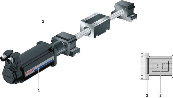
1 Motor
2 Mount
3 Coupling
Construction of timing belt side drive
The motors of all Drive Units can be attached using a timing belt side drive.
This makes the overall length shorter than when attaching the motor with a mount and coupling.
The space-saving, closed pulley housing serves as protection for the belt and as a motor bracket.
In addition, various gear ratios are also available (depending on size):
- i = 1
- i = 2
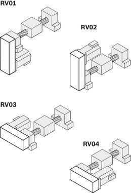
The timing belt side drive can be mounted in four different directions:
- bottom, top (RV01 and RV02)
- left, right (RV03 and RV04)

1 Pulley housing made of anodized aluminum frame
2 Timing belt
3 Motor
4 Timing belt pretensioned: Apply preload force Fpr to the motor (Fpr will be indicated on delivery)
5 Cover
6 Attaching the belt pulleys with tensioning units
7 Cover plate for timing belt side drive
Technical data
Note: Observe the document "Calculation" in the section "Project planning notes".
Load capacities and moments
| Size | AOK-032 | |||||||||||||
| d0 x P | mm | 32 x 5 | 32 x 10 | 32 x 20 | 32 x 32 | |||||||||
| Nuts | ZEM-E 1) | FEM-E-S | FEM-E-C | ZEM-E 1) | FEM-E-S | FEM-E-C | ZEM-E 1) | FEM-E-S | FEM-E-C | ZEM-E 1) | FEM-E-S | FEM-E-C | ||
| Nut housing | MGA | MGS | MGD | MGA | MGS | MGD | MGA | MGS | MGD | MGA | MGS | MGD | ||
| C | Nuts | N | 23310 | 34200 | 21240 | 14580 | 21240 | 21060 | 14490 | 21060 | ||||
| Fixed-bearing | N | 26000 | ||||||||||||
| 1) | Nut version ZEM-E only available with housing MGA |
General technical data
| Size | AOK-032 | ||||||||||||||
| d0 x P | mm | 32 x 5 | 32 x 10 | 32 x 20 | 32 x 32 | ||||||||||
| Nuts | ZEM-E 1) | FEM-E-S | FEM-E-C | ZEM-E 1) | FEM-E-S | FEM-E-C | ZEM-E 1) | FEM-E-S | FEM-E-C | ZEM-E 1) | FEM-E-S | FEM-E-C | |||
| Nut housing | MGA | MGS | MGD | MGA | MGS | MGD | MGA | MGS | MGD | MGA | MGS | MGD | |||
| Lc | Nuts | mm | - | 48 | - | 77 | - | 64 | 84 | - | 88 | 120 | |||
| Nuts and Nut Housings | mm | 150 | 63 | 83 | 150 | 77 | 83 | 150 | 75 | 84 | 150 | 114 | 120 | ||
| Lmax | Fixed/floating bearing | mm | 4000 | ||||||||||||
| Fixed bearing only | mm | 1500 | |||||||||||||
| Lad | Fixed/floating bearing | mm | 128 | ||||||||||||
| Fixed bearing only | mm | 74 | |||||||||||||
| smin 2) | mm | 150 | |||||||||||||
| mca | Nuts | kg | - | 0.54 | 0.62 | - | 0.72 | 0.84 | - | 1.02 | 0.9 | - | 1.4 | 1.21 | |
| Nuts and Nut Housings | kg | 3.33 | 2.29 | 2.89 | 3.27 | 2.47 | 3.11 | 3.36 | 3.39 | 3.17 | 3.39 | 3.77 | 3.48 | ||
| kg fix | Fixed/floating bearing | Aluminum | kg | 4.14 | |||||||||||
| Steel | kg | 9.65 | |||||||||||||
| Fixed bearing only | Aluminum | kg | 2.48 | ||||||||||||
| Steel | kg | 4.91 | |||||||||||||
| kg var | kg/mm | 056 | |||||||||||||
| 1) | Nut version ZEM-E only available with housing MGA |
| 2) | Minimum travel to ensure a reliable lubrication distribution. |
Calculation of the mass of the linear motion system
(without motor attachment, without motor)

Length calculation

Effective stroke

Drive data
| Size | AOK-032 | ||||||||||||||
| d0 x P | mm | 32 x 5 | 32 x 10 | 32 x 20 | 32 x 32 | ||||||||||
| Nuts | ZEM-E 1) | FEM-E-S | FEM-E-C | ZEM-E 1) | FEM-E-S | FEM-E-C | ZEM-E 1) | FEM-E-S | FEM-E-C | ZEM-E 1) | FEM-E-S | FEM-E-C | |||
| Nut housing | MGA | MGS | MGD | MGA | MGS | MGD | MGA | MGS | MGD | MGA | MGS | MGD | |||
| kJ fix | Nuts | kg·mm² | - | 129.9 | - | 131.3 | 131.6 | - | 139.9 | 138.6 | - | 165.8 | 160.9 | ||
| Nuts and Nut Housings | kg·mm² | 131.6 | 131 | 131.4 | 137.8 | 135.8 | 137.4 | 163.6 | 163.8 | 161.6 | 217.5 | 227.2 | 219.8 | ||
| kJ var | kg·mm | 0.7117 | |||||||||||||
| kJ m | mm² | 0.6333 | 2.533 | 10.1321 | 25.9382 | ||||||||||
| MRs | Fixed/floating bearing or fixed bearing only | C1 | Nm | 1.1 | 1.2 | 1.1 | |||||||||
| C2 | Nm | 1.3 | 1.5 | 1.3 | |||||||||||
| C3 | Nm | 1.3 | 1.5 | 1.3 | |||||||||||
| amax | m/s² | 17.9 | 30.7 | 50 | |||||||||||
| 1) | Nut version ZEM-E only available with housing MGA |
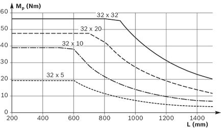
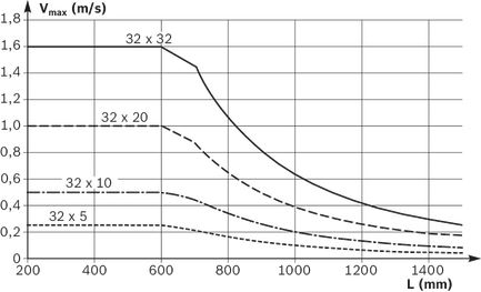
Note: For the max. drive torque Mp and max. speed vmax see section on "Diagrams / Characteristic curves".
Note: Observe the document "Calculation" in the section "Project planning notes".
Drive data for motor attachment using the timing belt side drive
| Size | Motor | d0 x P | up to L2) | Msd1) | Jsd | MRsd | msd | F | Bt | ||||
| mm | Fixed/floating bearing | Fixed bearing only | i = 1 | i = 2 | i = 1 | i = 2 | Nm | kg | mm | i = 1 | i = 2 | ||
| mm | mm | Nm | Nm | 10‑6 kgm2 Nm | 10‑6 kgm2 | ||||||||
| AOK-032 | MS2N06 | 32 x 5 | 2500 | 600 | 19,10 | 9,55 | 1400 | 260 | 0,5 | 3,2 | 116 | 25 AT5 | 32 AT5 |
| 32 x 10 | 3400 | 700 | 19,21 | 12,30 | |||||||||
| 32 x 20 | 4000 | 1100 | |||||||||||
| 32 x 32 | 1500 | ||||||||||||
| 1) | Values for Msd without making allowance for the motor torque. |
| 2) | For greater lengths, the permissible drive torque is determined from the variable-length value Mp of the Drive Unit in accordance with the diagram. See "Project planning notes" section. |
Drive data for motor attachment via mount and coupling
| Size | Motor | Coupling | Mount and coupling | |
| McN | Jc | mfc | ||
| Nm | 10‑6 kgm2 | kg | ||
| AOK-032 | MS2N06 | 50 | 210 | 1,8 |
Normal operating conditions
| Size | AOK-032 | |
| Permissible ambient temperature with Rexroth servo motor 1) | 0 °C ... +40 °C | |
| Permissible ambient temperature for mechanical system 2) | -10 °C ... +60 °C | |
| smin 3) | mm | 150 |
| 1) | Performance losses from 40°C |
| 2) | No passing below the dew point |
| 3) | Minimum travel to ensure a reliable lubrication distribution. |
Legend
| Symbol | Description | Unit |
| amax | Maximum acceleration travel | m/s2 |
| Bt | Belt type | - |
| C | Dynamic load capacity | N |
| d0 | Nominal diameter of ball screw drive | mm |
| F | Pulley housing width | mm |
| i | Timing belt side drive gear ratio | - |
| Jc | Mass moment of inertia of the coupling | kgm2 |
| Jsd | Reduced mass moment of inertia of timing belt side drive on the motor journal | kgm2 |
| kg fix | Constant for fixed portion of the mass | kg |
| kg var | Constant for variable-length portion of the mass | kg/mm |
| kJ fix | Constant for fixed-length portion of mass moment of inertia | kgmm2 |
| kJ m | Constant for mass-specific portion of mass moment of inertia | mm2 |
| kJ var | Constant for variable-length portion of mass moment of inertia | kgmm |
| L | Length | mm |
| Lad | Additional length | mm |
| Lc | Nut length/nut and housing length | mm |
| Lmax | Maximum length | mm |
| mca | Moved mass of system | kg |
| McN | Rated torque of coupling | Nm |
| mfc | Mass of mount and coupling | kg |
| Mp | Input torque | Nm |
| MRs | Frictional torque of the system | Nm |
| MRsd | Frictional torque of timing belt side drive on the motor journal | Nm |
| msd | Mass of timing belt side drive | kg |
| Msd | Maximum permissible drive torque of the timing belt side drive | Nm |
| P | Lead | mm |
| smin | Minimum travel | mm |
| vmax | Maximum speed | m/s |
Maximum values for each size
| Size | AOK-032 | |||
| amax | m/s² | 17.9 | 30.7 | 50 |
Diagrams/characteristic curves
Permissible drive torque MP
The values shown for Mp are valid under the following conditions:
- no radial load on the screw journals
Permissible drive torque MP with fixed and floating bearing
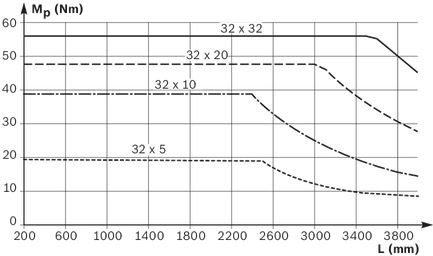
Permissible drive torque MP with fixed bearing only
Permissible speed vmax
Maximum permissible speed vmax with fixed and floating bearing

Maximum permissible speed vmax with fixed bearing only
Fields of application
Areas of application
Drive Units can be used in many ways as a drive axis for linear motion and positioning tasks in the application areas and industries below.
Possible applications
- pick and place
- handling systems
- placers, palletizers
- feeder units for machine tools
- testing and analysis systems
- feeder units in transfer lines
- offset slide mechanisms
Possible industries
- handling and assembly
- electronics and semiconductor industry
- automotive suppliers and manufacturers
- robotics and automation
- special machinery
- packaging technology
- plastics processing
- textile industry
Application-related notes
AOK and AGK Drive Units are designed for drive tasks only and can only absorb axial forces.
When using a Drive Unit, always make sure to include adequate, separate linear guides that can handle the structure being moved as well as the resulting reaction forces and torques.
This results in a linear motion unit (e.g. table top) that can be moved automatically thanks to an AOK or AGK Drive Unit.
Examples
Example of basic motion unit structure with table top and AOK Drive Unit

In this example, two separate linear guides, each with two Runner Blocks, absorb forces and torques so that when moving the structure only axial forces act on the Drive Unit (here AGK).

Follow the assembly instructions and installation tolerances in the "Installation" section.
Dimensions
All dimensions in mm. Drawings not to scale.
Straightness and flatness tolerance according to DIN EN 12020-02
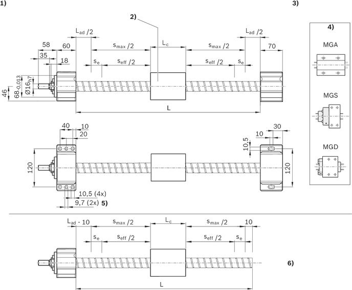
| 1) | Fixed bearing end (motor attachment) |
| 2) | Nut / nut and housing Selection see document "Configuration and ordering" in the section "Ordering information" Dimensions see corresponding dimensional drawings |
| 3) | Floating bearing end |
| 4) | Nut housing |
| 5) | pre-drilled for pin hole |
| 6) | No floating bearing |
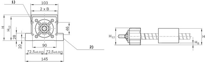
| 1) | M8 - 15 deep (4x) |
| 2) | Reference edges (on two sides) |
Lad = Längenzuschlag (siehe Kapitel „Technische Daten“)
Dimensions
| Size | AOK-032 | ||||||||||||
| d0 x P | mm | 32 x 5 | 32 x 10 | 32 x 20 | 32 x 32 | ||||||||
| Nuts | ZEM-E 1) | FEM-E-S | FEM-E-C | ZEM-E 1) | FEM-E-S | FEM-E-C | ZEM-E 1) | FEM-E-S | FEM-E-C | ZEM-E 1) | FEM-E-S | FEM-E-C | |
| Nut housing | MGA | MGS | MGD | MGA | MGS | MGD | MGA | MGS | MGD | MGA | MGS | MGD | |
| B | mm | 50 | 47.5 | 50 | 47.5 | 50 | 52.5 | 50 | 52.5 | 50 | |||
| Tolerance for B | mm | ± 0.01 | |||||||||||
| H | mm | 95 | 84 | 81 | 95 | 84 | 81 | 95 | 88 | 81 | 95 | 88 | 81 |
| H12 | mm | 91 | |||||||||||
| Tolerance for H12 | mm | ± 0.15 | |||||||||||
| HB | mm | 15 | 9 | 11 | 15 | 9 | 11 | 15 | 6 | 11 | 15 | 6 | 11 |
| Lc | mm | 150 | 63 | 83 | 150 | 77 | 83 | 150 | 75 | 84 | 150 | 114 | 120 |
| 1) | Nut version ZEM-E only available with housing MGA |
dimensional drawings with nut and housing

| 1) | Figure 1 (MGA) |
| 2) | Figure 2 (MGS, MGD) |
| 3) | Figure 3 a) / Figure 3 b) (MGS, MGD) |
| 4) | Countersink for O-ring 7 x 1.5 |
| 5) | Lube port at flange center |
| 6) | Dimension drawing for all Nut Housings (Figure 1, 2, 3) |
| 7) | S1 = 4x thread |
| 8) | S = 4x drill hole |
Dimensions
| Size | AOK-032 | ||||||||||||
| d0 x P | mm | 32 x 5 | 32 x 10 | 32 x 20 | 32 x 32 | ||||||||
| Nuts | ZEM-E 1) | FEM-E-S | FEM-E-C | ZEM-E 1) | FEM-E-S | FEM-E-C | ZEM-E 1) | FEM-E-S | FEM-E-C | ZEM-E 1) | FEM-E-S | FEM-E-C | |
| Nut housing | MGA | MGS | MGD | MGA | MGS | MGD | MGA | MGS | MGD | MGA | MGS | MGD | |
| Picture | 1 | 3 b) | 1 | 3 a) | 3 b) | 1 | 3 b) | 3 a) | 1 | 2 | 3 a) | ||
| A | mm | - | 50 | 70 | - | 50 | 70 | - | 60 | 70 | - | 60 | 70 |
| B | mm | 50 | 47.5 | 50 | 47.5 | 50 | 52.5 | 50 | 52.5 | 50 | |||
| Tolerance for B | mm | ± 0.01 | |||||||||||
| C | mm | - | 13 | - | 13 | - | 15 | 13 | - | 54 | 13 | ||
| E1 | mm | 75 | 72 | 75 | 72 | 75 | 82 | 75 | 82 | 75 | |||
| Tolerance for E1 | mm | - | ± 0.1 | - | ± 0.1 | - | ± 0.1 | - | ± 0.1 | ||||
| E2 | mm | 100 | 26 | 30 | 100 | 26 | 30 | 100 | 30 | 100 | 30 | ||
| Tolerance for E2 | mm | - | ± 0.1 | - | ± 0.1 | - | ± 0.1 | - | ± 0.1 | ||||
| H1 | mm | 80 | 75 | 70 | 80 | 75 | 70 | 80 | 82 | 70 | 80 | 82 | 70 |
| H2 | mm | 10 | 12 | ||||||||||
| Lc | mm | 150 | 63 | 83 | 150 | 77 | 83 | 150 | 75 | 84 | 150 | 114 | 120 |
| L1 | mm | 66 | 61 | 52 | 66 | 61 | 52 | 66 | 64 | 52 | 66 | 64 | 52 |
| N | mm | 25 | 12 | 27 | 25 | 15 | 27 | 25 | 15 | 27 | 25 | 15 | 27 |
| S1 | M12 | M16 | M12 | M16 | M12 | M16 | M12 | M16 | |||||
| S | mm | 10.5 | 13 | 10.5 | 13 | 10.5 | 13 | 10.5 | 13 | ||||
| T1 | mm | 18 | 15 | 20 | 18 | 15 | 20 | 18 | 20 | 18 | 20 | ||
| 1) | Nut version ZEM-E only available with housing MGA |
dimensional drawings with nut
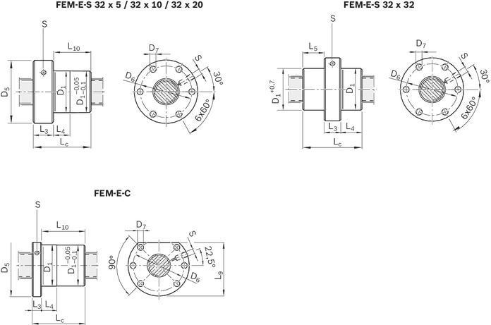
Dimensions
| Size | AOK-032 | |||||||||||||
| d0 x P | mm | 32 x 5 | 32 x 10 | 32 x 20 | 32 x 32 | |||||||||
| Nuts | ZEM-E 1) | FEM-E-S | FEM-E-C | ZEM-E 1) | FEM-E-S | FEM-E-C | ZEM-E 1) | FEM-E-S | FEM-E-C | ZEM-E 1) | FEM-E-S | FEM-E-C | ||
| D1 | g6 | mm | - | 48 | 50 | - | 48 | 50 | - | 56 | 50 | - | 56 | 50 |
| D5 | mm | - | 73 | 80 | - | 73 | 80 | - | 80 | - | 80 | |||
| D6 | mm | - | 60 | 65 | - | 60 | 65 | - | 60 | 65 | - | 60 | 65 | |
| D7 | mm | - | 6.6 | 9 | - | 6.6 | 9 | - | 6.6 | 9 | - | 6.6 | 9 | |
| Lc | mm | - | 48 | - | 77 | - | 64 | 84 | - | 88 | 120 | |||
| L3 | mm | - | 13 | - | 13 | - | 15 | 13 | - | 20 | 13 | |||
| L4 | mm | - | 10 | - | 16 | - | 25 | - | 34 | 40 | ||||
| L5 | cm | - | 34 | - | ||||||||||
| L9 | mm | - | 71 | - | 71 | - | 71 | - | 71 | |||||
| L10 | mm | - | 35 | - | 64 | - | 49 | 71 | - | 107 | ||||
| S | - | M6 2) | - | M6 2) | - | M6 2) | - | M6 2) | ||||||
| 1) | Nut version ZEM-E only available with housing MGA |
| 2) | Lube hole (S) (in flange center on FEM-E-S, FEM-E-C); lube port machining: Flat surface L3 ≤ 15 mm, countersink L3 > 15 mm. |
Project planning information
Calculation example
Mounting
Mounting tolerances
Parallelism of customer-built attachments, pillow blocks and rail guides
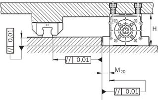
Dimensions
| Size | AOK-032 | ||||||||||||
| d0 x P | mm | 32 x 5 | 32 x 10 | 32 x 20 | 32 x 32 | ||||||||
| Nuts | ZEM-E 1) | FEM-E-S | FEM-E-C | ZEM-E 1) | FEM-E-S | FEM-E-C | ZEM-E 1) | FEM-E-S | FEM-E-C | ZEM-E 1) | FEM-E-S | FEM-E-C | |
| Nut housing | MGA | MGS | MGD | MGA | MGS | MGD | MGA | MGS | MGD | MGA | MGS | MGD | |
| H | mm | 95 | 84 | 81 | 95 | 84 | 81 | 95 | 88 | 81 | 95 | 88 | 81 |
| Tolerance for H | mm | ± 0.01 | |||||||||||
| M20 | mm | 22.5 | 25 | 22.5 | 25 | 22.5 | 20 | 22.5 | 20 | 22.5 | |||
| Tolerance for M20 | mm | ± 0.01 | |||||||||||
| 1) | Nut version ZEM-E only available with housing MGA |
Commissioning
Parameterization (start-up)
The nameplate contains reference information on the production of the linear motion system as well as technical start-up parameters.
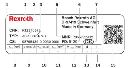
| Position | Symbol | Description | Unit |
| 1 | CNR | Customer's part number | - |
| 2 | TYP | Type designation | - |
| 3 | 032 | Size | - |
| 4 | CS | Customer information | - |
| 5 | MNR | Part No. | - |
| 6 | FD | Manufacturing date | - |
| 7 | 7210 | Manufacturing location | - |
| 8 | smax | Maximum travel range | mm |
| 9 | u | Lead constant without motor attachment | mm/U |
| 10 | vmax | Maximum speed without gear | m/s |
| 11 | amax | Maximum acceleration without gear | m/s2 |
| 12 | M1max | Maximum drive torque at motor journal | Nm |
| 13 | d | Direction of motor rotation to move in positive (+) direction CW = clockwise CCW = counter clockwise  | - |
| 14 | i | Gear ratio | - |
| 15 | QR code | - |
Maintenance
Lubrication
Delivery notes
Condition on delivery
Drive Units come ready-mounted.
Motor attachment
If a combination of motor and motor attachment has been selected, then the attachment of the components is done as shown in the figure which also shows the location of the motor connector.
Motor attachments ordered without a motor must be assembled by the customer.
All necessary instructions and parameters for professional assembly are included.
AOK (example)
Mount and coupling (MF01)
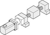
Timing belt side drive (RV01–RV04)
Selectable options
switch and socket with plug are enclosed with the delivery.
Lubrication
Drive Units are delivered with initial greasing.
For further information, see the "Maintenance" section.
Documentation
Each Drive Unit will be delivered with the corresponding documentation.
Safety Instructions
Required and supplementary documentation
For further instructions and information, please refer to the documentation for this product.
You can find PDF files of these documents on the Internet at www.boschrexroth.com/mediadirectory.
We would also be happy to send you the documents that you want.
If you are unsure about using this product, please contact Bosch Rexroth.
Motor attachment
Version

Abmessungen
| Version | Motor code | Lf | ▢ E |
| mm | mm | ||
| MF01 | MS2N06-B1BNN | 125 | see dimension ▢ A → "Motors" chapter |
| MS2N06-C0BTN | |||
| MS2N06-D0BRN | |||
| MS2N06-D1BNN |
Abmessungen
| Version | Motor code | E | F | G | K | Lsd | ||
| i = 1 | i = 2 | i = 1 | i = 2 | |||||
| mm | mm | mm | mm | mm | mm | mm | ||
| RV01, RV02, | MS2N06-B1BNN | 165 | - | 116 | 66 | 59 | 300 | - |
| MS2N06-C0BTN | - | 162 | - | 300 | ||||
| MS2N06-D1BNN | 165 | - | 300 | - | ||||
Measurement and test reports
Downloads
 | Declaration of Incorporation for single axis Linear Motion Systems Certificate | R320103141 | 2020-06-01 | All languages | PDF | 409k Product Groups: Linear axes and electromechanical cylinders |
| Safety Instructions for Linear Motion Systems Manual | R320103152_en | 2015-01-01 | English | PDF | 593k Product Groups: Linear axes and electromechanical cylinders |
| Drive Units AOK Manual | R320103915 | 2007-10-01 | English, French, German, Italian | PDF | 2.9MB Product Groups: Drive Units |
| Unidad de accionamiento AOK Manual | R320103916 | 2007-10-01 | Spanish | PDF | 2.6MB Product Groups: Drive Units |
| Drive Units with Ball Screw Drives Catalog | R999001326 | 2017-06-01 | English | PDF | 13.8MB Product Groups: Drive Units |


Нет отзывов об этом товаре.