
Доступно к заказу
Цена по запросу
И выбери подходящего.
Description
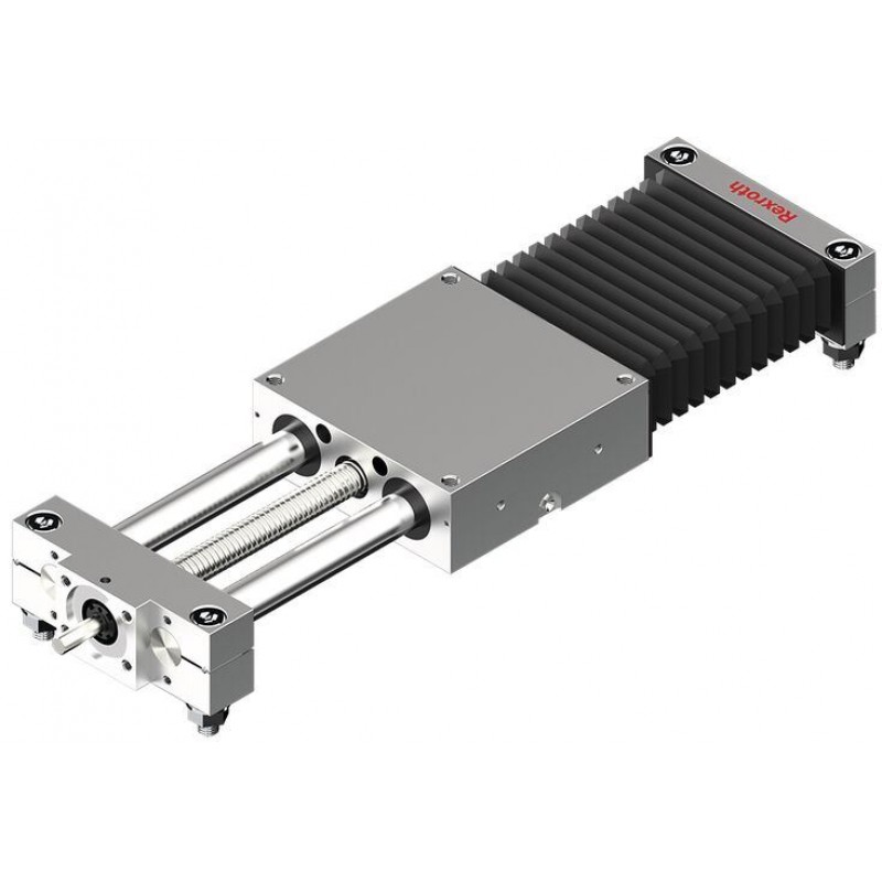
- Closed-type format for self-supporting installation
- High feed system power
- Particularly suitable for environments with a heavy contamination load (closed bellows)
- High traversing speed due to large leads
- Rexroth precision ball screw assembly in rolled design tolerance grade T7 in accordance with DIN 69051 with backlash-free cylindrical nut
Features
- Inexpensive maintenance thanks to the one-point lubrication (grease lubrication) on two sides of the guide system
- Simple motor mounting using centering recess and thread
- Wide range of accessories available
Product description
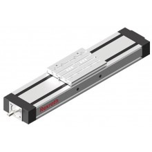
Linear motion slides are an inexpensive solution for a wide variety of applications. Linear motion slide guides consist of linear bushings that ensure quiet travel and a long service life. Linear motion slides with a closed design are suitable for self-supporting uses. Here, the guide is connected to the mounting base at both ends via shaft support blocks.
Structural design
- Fixed-bearing end block
- Ball screw assembly with backlash-free, cylindrical single nut
- Carriage with four super linear bushings (size 8-65 with standard linear bushings)
- Polyurethane protective bellows
- Floating bearing end block
Attachment parts
- Motor with control units
- Switch (inductive and mechanical)
- Socket and plug
- Cable duct made of aluminum profile
Technical data
Maximum values for each size
| Size | SGK-085 | SGK-100 | SGK-130 | SGK-160 | SGK-180 | SGK-230 | SGK-280 | |
| C | N | 2700 | 3310 | 6560 | 12830 | 15600 | 26770 | 39180 |
| Cbs | N | 2200 | 3800 | 12300 | 15700 | 31700 | ||
| Cfb | N | 5280 | 13400 | 17000 | 26000 | |||
| Mt | Nm | 56 | 89 | 236 | 564 | 748 | 1633 | 2977 |
| ML | Nm | 62 | 94 | 249 | 596 | 787 | 1860 | 3271 |
| Mx max | Nm | 18 | 29 | 76 | 192 | 268 | 531 | 983 |
| My max | Nm | 19 | 30 | 80 | 203 | 282 | 605 | 1080 |
| Mz max | Nm | 19 | 30 | 80 | 203 | 282 | 605 | 1080 |
| Fy max | N | 840 | 1060 | 2100 | 4360 | 5580 | 8700 | 12940 |
| Fz max | N | 840 | 1060 | 2100 | 4360 | 5580 | 8700 | 12940 |
| Lmax | mm | 1000 | 1500 | 2500 | 3000 | 4000 | ||
| amax | m/s² | 27 | ||||||
| vmax | m/s | 0.25 | 1 | 1.24 | 1.26 | 1.6 | ||
| Maximum values depends on the selected configuration. |
Legend
| Symbol | Description | Unit |
| C | Dynamic load capacity, linear guide | N |
| Cbs | Dynamic load capacity, ball screw drive | N |
| Cfb | Dynamic load capacity, fixed bearing | N |
| Mt | Dynamic torsional moment load capacity | Nm |
| ML | Dynamic longitudinal moment load capacity | Nm |
| Mx max | Maximum admissible torsional moment around the x-axis | Nm |
| My max | Maximum admissible torsional moment around the y-axis | Nm |
| Mz max | Maximum admissible torsional moment around the z-axis | Nm |
| Fy max | Maximum dynamic load in y-direction | N |
| Fz max | Maximum dynamic load in z-direction | N |
| Lmax | Maximum length | mm |
| amax | Maximum acceleration travel | m/s2 |
| vmax | Maximum permissible speed | m/s |
Mounting
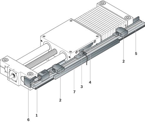
Switching system overview
1 Socket and plug
2 Mechanical switch (with attachments)
3 Proximity switch (with attachments)
4 Switching cam
5 Profiled support
6 Mounting bracket
7 Cable duct (aluminum alloy)
Switch mounting arrangements
The switching position indicates the position of the carriage center (TM) after moving. The zero point is at L / 2.
Maximum switching position
= 0.5 · travel path max. – excess travel
For safe operation of the Linear Motion Slide, the excess travel must be greater than the braking distance.
The acceleration travel can be adopted as the guideline value for the braking distance.
Recommended standard configuration:
- 2 mechanical switches
- 1 proximity switch
Push the mounting plates with switches into the slot and secure with the screws and square nuts.
Observe the lowest possible switching distance:
mechanical / mechanical = 62 mm
mechanical / proximity = 49 mm
proximity / proximity = 35 mm
Attention: For this, the mounting plates must be mirror-inverted.
Mounting side of the switches:

| 1) | Fixed bearing end |
| 2) | links (L) |
| 3) | right (R) |
| 4) | Direction of travel |
| 5) | Floating bearing end |
1 Socket with plug
2 Proximity switch
3 Mechanical switch
4 Switching cam
5 Profiled support
Switch mounting:
- Adjust the distance dimensions for the mechanical and proximity switches during assembly.
- In case of special operating conditions (vibrations, switches in the middle of the travel path), support the profiled support if necessary.

| 1) | View, mechanical switch |
| 2) | View, Proximity switch |
| 3) | View, mounting bracket with cable duct |
| 4) | adjust for mounting |
| 5) | 37 for SGK/SOK-085 |
| 6) | Cable duct |
Dimensions mechanical switch (mm)
|
| A | B | C | C11) | D | D11) | E |
| SGK-085 | 5,5 | 27 |
| 4 |
| 3,5 | 40 |
| SGK-100 | 5,5 | 30 |
| 6 | 0,5 |
| 40 |
| SGK-130 | 6,5 | 40 | 4 |
| 10,5 |
| 40 |
| SGK-160 | 6,5 | 40 | 7 |
| 13,5 |
| 40 |
| SGK-180 | 7,5 | 40 | 14 |
| 20,5 |
| 40 |
| SGK-230 | 9,0 | 40 | 2 |
| 8,5 |
| 40 |
| SGK-280 | 9,0 | 40 | 2 |
| 8,5 |
| 40 |
| 1) | The switch protrudes over the top edge of the carriage. |
Determine switching position
The switching position is derived from:
- Mounting side:
The switches can be attached on the left (L) or right (R).
- Direction of travel:
The switches can be attached on the minus (–) or positive (+) range.
- Switching distance:
The switching distance is the distance between the carriage center (CC) and the zero point (0) when a switch is activated (given in mm).
Example
Effective stroke = 500 mm
Limit switch:
Switching position 1st switch = + 250 mm
Switching position 3rd switch = – 250 mm
Positioning switch:
Switching position 2nd switch = – 150 mm
Length L
For calculation of the length, see "Length calculation" in the section “Dimensions”.
Switching position

| 1) | links (L) |
| 2) | right (R) |
| 3) | Direction of travel |
| 4) | Stroke |
Switching position sample

Accessories
Proximity sensor with free line end
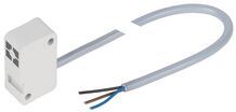
Proximity sensor with free line end
Additional components for inductive sensor

Additional components for inductive sensor
Mechanical switch

Mechanical switch
Socket and plug
R141400061

Socket and plug
R141400061
Switching angle and fastening bracket

Switching angle and fastening bracket
Profiled support
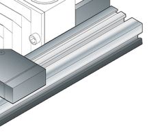
Profiled support
Safety Instructions
Required and supplementary documentation
For further instructions and information, please refer to the documentation for this product.
You can find PDF files of these documents on the Internet at www.boschrexroth.com/mediadirectory.
We would also be happy to send you the documents that you want.
If you are unsure about using this product, please contact Bosch Rexroth.
Ordering codes
Order overview
| Size | Part number | Short product name | CAD data | Buy |
| SGK-085 | R026100000 | SGK-085-NN-1 | ||
| SGK-100 | R026110000 | SGK-100-NN-1 | ||
| SGK-130 | R026120000 | SGK-130-NN-1 | ||
| SGK-160 | R026130000 | SGK-160-NN-1 | ||
| SGK-180 | R026140000 | SGK-180-NN-1 | ||
| SGK-230 | R026150000 | SGK-230-NN-1 | ||
| SGK-280 | R026160000 | SGK-280-NN-1 |
Explanation of short product name
| Linear Motion Slides SGK example | SGK-130-NN-1 | |
| System | S | Linear Motion Slides |
| Design type | G | Closed |
| Drive | K | Ball screw assembly |
| Size | 130 | 085/100/130/160/180/230/280 |
| Version | NN | Normal version |
| Generation | 1 | Product generation 1 |
Downloads


Нет отзывов об этом товаре.