
Артикул: RX7394
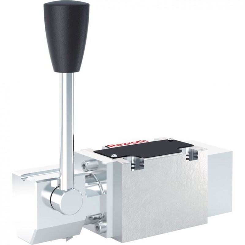
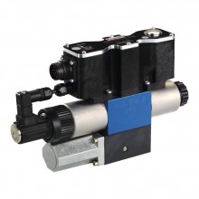
4/3, 4/2 and 3/2 directional valve with manual actuation WMM 6...XC
Доступно к заказу
Цена по запросу
И выбери подходящего.
Description
- Size 6
- Component series 5X
- Maximum operating pressure 315 bar
- Maximum flow 60 l/min
- Area of application in accordance with the Explosion Protection Directive 2014/34/EU: I M2, II 2G, II 2D, II 3G, II 3D
- Type of protection of the valve solenoids: c (EN 13463-5)
Features
- Direct operated directional spool valve for intended use in potentially explosive atmospheres
- Actuation elements: hand lever
- Porting pattern according to DIN 24340 form A (without locating hole)
- Porting pattern according to ISO 4401-03-02-0-05 (with locating hole)
Product description
Valves of type WMM 6...XC are manually actuated directional spool valves.
They control the start, stop and direction of a flow.
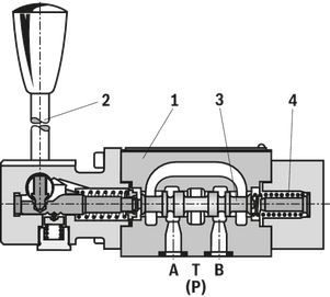
The directional valves basically consist of housing (1), an actuation element (2) (hand lever), control spool (3) and one or two return springs (4).
When de-energized, the control spool (3) is held in the central position or in the initial position by the return springs (4).
The control spool (3) is moved to the desired spool position by means of the actuation elements.
Detent
Directional valves with hand lever are optionally available as 2 or 3 position valves with detent. If actuation elements with detent are used, each spool position can be locked, depending on the valve type.
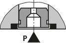
Throttle insert
The use of a throttle insert is required when due to prevailing operating conditions, flows can occur during the switching processes, which exceed the performance limit of the valve.
It is inserted in channel P of the directional valve.
Type . WMM 6 ..5X/..B..
Type 4WMM 6 D5X/FXC...
Type code
| 01 | 02 | 03 | 04 | 05 | 06 | 07 | 08 | 09 | 10 | |
| WMM 6 | 6 | 5X | / | XC |
| 01 | 3 main ports | 3 |
| 4 main ports | 4 | |
| Type of actuation | ||
| 02 | Hand lever | WMM |
| 03 | Size 6 | 6 |
| 04 | Symbols; for the possible version, see "Symbols/Circuit diagrams" | |
| 05 | Component series 50 … 59 (50 … 59: unchanged installation and connection dimensions) | 5X |
| 06 | With spring return | no code |
| With detent | F | |
| 07 | Valves in explosion-protected design; for details, see "Information on explosion protection", in chapter "Technical data" | XC |
| 08 | Without throttle insert | no code |
| Throttle Ø 0.8 mm | B082) | |
| Throttle Ø 1.0 mm | B102) | |
| Throttle Ø 1.2 mm | B122) | |
| Seal material | ||
| 09 | NBR seals | no code |
| FKM seals | V | |
| Observe compatibility of seals with hydraulic fluid used. | ||
| 10 | Without locating hole | no code |
| With locating hole | /60 1) | |
| with locating hole and grooved pin ISO 8741-3x8-St | /62 | |
| 1) Grooved pin ISO 8741-3x8-St-A2C, material no. R900005076 (separate order) | |
| 2) Use if volume flow > performance limits of the valve, effective in channel P. |
included in the scope of delivery:
Valve operating instructions with declaration of conformity in part III
Technical data
general
| Size | 6 | ||
| Weight (approx.) | kg | 1.4 | |
| Installation position | any | ||
| Ambient temperature range | NBR seals | °C | -30 … +80 |
| FKM seals | °C | -20 … +80 | |
| Hydraulic fluid | Classification | Suitable sealing materials | Standards | |
| Mineral oil | HL, HLP | FKM, NBR | DIN 51524 | |
| Bio-degradable | Insoluble in water | HEES (synthetic esters) | FKM | VDMA 24568 |
| HETG (rape seed oil) | FKM, NBR | |||
| Soluble in water | HEPG (polyglycols) | FKM | VDMA 24568 | |
| Containing water | Containing water | HFC | NBR | ISO 12922 |
| Other hydraulic fluids on request | ||||
Information on explosion protection
| Area of application according to directive 2014/34/EU | IM2; II2G; II2D; II3G; II3D | |
| Type of protection valve | c (EN 13463-5) | |
| Maximum surface temperature 1) | °C | 100 |
| Temperature class 1) | T4 | |
| 1) | The specified values refer to the maximum hydraulic fluid and ambient temperature. Due to a maximum pressure drop across the valve, the surface temperature exceeds the hydraulic fluid temperature by 20 K, i. e. using the valve in T6 is possible if the hydraulic fluid temperature and the ambient temperature do not exceed 60 °C. |
Actuating force/torque
| Operating force | without tank pressure, with/without detent | N | 20 |
| at a tank pressure of 150 bar | N | 30 |
hydraulic
| Size | 6 | ||
| Maximum operating pressure | Port P | bar | 315 |
| Port A | bar | 315 | |
| Port B | bar | 315 | |
| Port T 1) | bar | 100 | |
| Maximum flow | l/min | 60 | |
| Flow cross-section | Symbol Q | approx. 6 % of nominal cross-section | |
| Symbol W | approx. 3 % of nominal cross-section | ||
| Hydraulic fluid | see table | ||
| Hydraulic fluid temperature range | NBR seals | °C | -30 … +80 |
| FKM seals | °C | -20 … +80 | |
| Viscosity range | mm²/s | 2.8 … 500 | |
| Maximum admissible degree of contamination of the hydraulic fluid 2) | Class 20/18/15 according to ISO 4406 (c) | ||
| 1) | With symbols A or B, port T must be used as leakage oil connection if the operating pressure exceeds the admissible tank pressure. 2 bar minimum preload pressure required. |
| 2) | The cleanliness classes specified for the components must be adhered to in hydraulic systems. Effective filtration prevents faults and simultaneously increases the life cycle of the components. For the selection of the filters, see www.boschrexroth.com/filter. |
(For applications outside these values, please consult us!)
Diagrams/characteristic curves
(measured with HLP46, ϑOil = 40 °C ± 5 °C)
Δp-qV characteristic curves
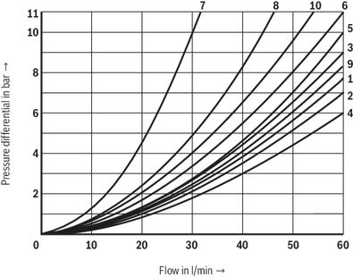
| Further characteristic curves: | |
| 7 | Spool symbol “R” in spool position "b" (A → B) |
| 8 | Spool symbols “G” and “T” in central position (P → T) |
| Characteristic curve | Symbol |
| 1 | E, E1, M, J, L, Q, U, W, C, D, Y, G, H, R |
| 2 | A, B |
| 3 | V |
| 4 | F, P |
| 5 | T |
| Symbols | Direction of flow | |||
| P-A | P-B | A-T | B-T | |
| A | 3 | 3 | - | - |
| B | 3 | 3 | - | - |
| C | 1 | 1 | 3 | 1 |
| D | 5 | 5 | 3 | 3 |
| E | 3 | 3 | 1 | 1 |
| F | 1 | 3 | 1 | 1 |
| G | 6 | 6 | 9 | 9 |
| H | 2 | 4 | 2 | 2 |
| J | 1 | 1 | 2 | 1 |
| L | 3 | 3 | 4 | 9 |
| M | 2 | 4 | 3 | 3 |
| P | 3 | 1 | 1 | 1 |
| Q | 1 | 1 | 2 | 1 |
| R | 5 | 5 | 4 | - |
| T | 10 | 10 | 9 | 9 |
| U | 3 | 3 | 9 | 4 |
| V | 1 | 2 | 1 | 1 |
| W | 1 | 1 | 2 | 2 |
| Y | 5 | 5 | 3 | 3 |
Performance limits
(measured with HLP46, ϑOil = 40 ±5 °C)
The specified switching power limits are valid for use with two directions of flow (e. g. from P to A and simultaneous return flow from B to T).
Due to the flow forces acting within the valves, the admissible switching power limit may be considerably lower with only one direction of flow (e. g. from P to A while port B is blocked)!
In such use cases, please consult us!
Type WMM 6...XC- spring return

| Characteristic curve | Symbol |
| 1 | E, E1, M, J, L, Q, U, W, C, D, Y, G, H, R |
| 2 | A, B |
| 3 | V |
| 4 | F, P |
| 5 | T |
| Symbols | Direction of flow | |||
| P-A | P-B | A-T | B-T | |
| A | 3 | 3 | - | - |
| B | 3 | 3 | - | - |
| C | 1 | 1 | 3 | 1 |
| D | 5 | 5 | 3 | 3 |
| E | 3 | 3 | 1 | 1 |
| F | 1 | 3 | 1 | 1 |
| G | 6 | 6 | 9 | 9 |
| H | 2 | 4 | 2 | 2 |
| J | 1 | 1 | 2 | 1 |
| L | 3 | 3 | 4 | 9 |
| M | 2 | 4 | 3 | 3 |
| P | 3 | 1 | 1 | 1 |
| Q | 1 | 1 | 2 | 1 |
| R | 5 | 5 | 4 | - |
| T | 10 | 10 | 9 | 9 |
| U | 3 | 3 | 9 | 4 |
| V | 1 | 2 | 1 | 1 |
| W | 1 | 1 | 2 | 2 |
| Y | 5 | 5 | 3 | 3 |
Type WMM 6...XC - with detent
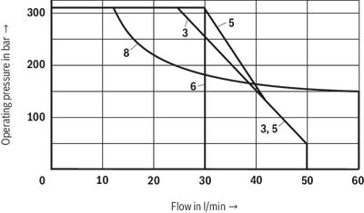
| Characteristic curve | Symbol |
| 3 | A, B |
| 5 | F |
| 6 | V |
| 8 | R |
Type WMM 6...XC - with detent

| Characteristic curve | Symbol |
| 1 | E1, M, H, C, D, Y |
| 2 | E, J, Q, L, U, W |
| 4 | G, T |
| 7 | P |
| 9 | T |
Symbols/Circuit diagrams


| 1) | Example: – Symbol E with spool position "a" → ordering code ..EA.. – Symbol E with spool position “b” → ordering code ..EB.. |
| 2) | Symbol E1-: P → A/B pre-opening |
Caution in conjunction with differential cylinders due to pressure intensification!
| Type of actuation |
| Hand lever |
Dimensions
Dimensions in mm
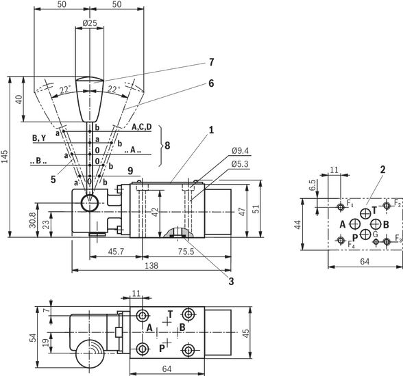
 Required surface quality of the valve contact surface |
| 1 | Name plate |
| 2 | Porting pattern according to DIN 24340 form A (without locating hole), or ISO 4401-03-02-0-05 (with locating hole) |
| 3 | Identical seal rings for ports A, B, P, T |
| 5 | Spool position “a” |
| 6 | Spool position “b” |
| 7 | Spool position “0”, “a” and “b” (a and b for 2 pos. valves) |
| 8 | 2 pos. valve |
| 9 | 3 pos. valve |
Valve mounting screws
For reasons of stability, exclusively the following valve mounting screws are to be used:
4 hexagon socket head cap screws
ISO 4762-M5x50-10.9-flZn-240h-L
(friction coefficient 0.09-0.14 according to VDA 235-101)
Material no. R913000064
(must be ordered separately)
Downloads
 | Directional spool valves, direct operated, with manual actuation Data Sheet | RE22280-XC | 2019-10-01 | English | PDF | 528k Product Groups: Direct operated Type WMM ...XC |
| Directional spool valves, direct operated, with manual actuation, Type WMM6..5X/...XC..., Operating instructions Manual | RE22280-XC-B | 2019-12-03 | English | PDF | 1.2MB Product Groups: Direct operated |
| Explosion-protected hydraulic products for industrial and mobile applications Brochure | R999000373 | 2017-03-01 | English | PDF | 5.8MB Product Groups: Pumps, CD - single rod cylinder, Proportional, high-response and servo valves, Axial piston pumps, Mobile controls Product overview |

Цена по запросу
Цена по запросу
Цена по запросу
Нет отзывов об этом товаре.