
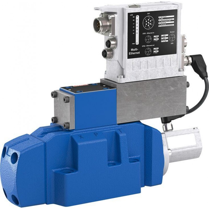
Артикул: RX7600
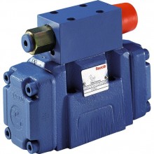
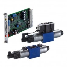
Directional control valve, pilot-operated, with integrated fieldbus (IFB-Multi Ethernet) 4WRLF
Доступно к заказу
Цена по запросу
И выбери подходящего.
Description
- Size 10 … 27
- Component series 4X
- Maximum operating pressure 350 bar
- Maximum flow 1850 l/min
- Nominal flow 60 … 600 l/min
Features
- Open
- Integrated fieldbus (IFB Multi-Ethernet)
- Bus connection/service interface (Sercos, EtherCAT, EtherNet/IP, PROFINET RT, POWERLINK, VARAN) - Scalable
- 2 configurable analog pressure sensor inputs - Precise
- Integrated pressure-force control
- High response sensitivity and little hysteresis - Safe
- Internal safety function (can be used up to category 4/PL e according to EN13849-1)
- CE conformity according to EMC Directive 2014/30/EU
Product description
General information
The pilot-operated IFB Multi-Ethernet valve (Integrated Fieldbbus) is a digital directional control valve with integrated fieldbus:
- The following operating modes are possible:
- Standard:
- Valve direct control
- Flow control
- Version "5" (with external pressure sensors):
- Pressure/force control
- Active damping
- Substitutional control (flow - pressure/force); pQ function (flow-controlled)
- Command value presetting is done via the Ethernet interface (X7E1 or X7E2)
- The feedback information of the actual value signals to the superior control system is provided via the Ethernet interface (X7E1 or X7E2)
- The controller parameters are set via the Ethernet interface (X7E1 or X7E2)
Set-up
The directional control valve with IFB Multi-Ethernet electronics mainly consists of:
- Pilot control valve (1) with control spool and sleeve in servo quality
- Main stage (2) with centering springs and position feedback
- Integrated fieldbus (3) with:
- connector, voltage supply, safety shut-down (XH1)
- Ethernet interfaces (X7E1, X7E2)
- analog sensor interfaces (X2N)
- interface for the position transducer of the main stage (X8A)
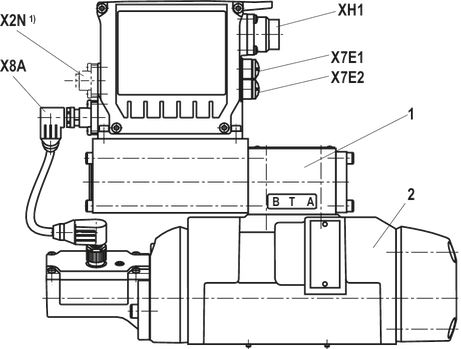
| 1) | Only version "5" |
Function (symbol V, V1- and Q3-)
When the control solenoid of the pilot control valve is de-energized, its spring-operated control spool is in the "fail safe" position. The control spool of the main valve is in the spring-centered offset position at approx. 6% of the stroke in direction P→B/A→T.
The integrated electronics (OBE) compare the specified command value to the position actual value of the control spool of the main stage. In case of a control deviation, the control solenoid of the pilot control valve is activated and its control spool is adjusted.
The flow which is activated via the control cross-sections at the pilot control valve leads to an adjustment of the control spool of the main valve. The stroke/control cross-section of the main valve is regulated proportionally to the command value. In case of a command value presetting of 0%, the electronics adjust the control spool of the main valve to central position.
The pilot oil supply in the pilot control valve is either internal via port P or external via port X. The feedback can be internal via port T or external via port Y to the tank.
Switching off the release (symbol V and V1-)
The control spool of the main valve is not in a safe position after the release is switched off. The enable acknowledgement is not set (pin C). If the supply voltage fails or in case of cable break, the integrated electronics will de-energize the control solenoid, the pilot control spool will move to the fail-safe position and will unload the pilot oil chambers of the main valve. Operated by the spring, the control spool of the main valve will move to the offset position (approx. 6% P→B/A→T).
Function (symbol E. and W.)
When the control solenoid of the pilot control valve is de-energized, its spring-operated control spool is in the "fail safe" position. The control spool of the main valve is in spring-centered central position.
The integrated electronics (OBE) compare the specified command value to the position actual value of the control spool of the main stage. In case of a control deviation, the control solenoid of the pilot control valve is activated and its control spool is adjusted.
The flow which is activated via the control cross-sections at the pilot control valve leads to an adjustment of the control spool of the main valve. The stroke/control cross-section of the main valve is regulated proportionally to the command value.
The pilot oil supply in the pilot control valve is either internal via port P or external via port X. The feedback can be internal via port T or external via port Y to the tank.
Switching off the release (symbol E., W. and Q3-)
If the control spool of the main valve is in the safe position, the enable acknowledgement is set (pin C).
If the control spool of the main valve leaves the safe position or the release is set, the enable acknowledgement expires. If the supply voltage fails or in case of cable break, the integrated electronics will de-energize the control solenoid, the pilot control spool will move to the fail-safe position and will unload the pilot oil chambers of the main valve. Operated by the spring, the control spool
of the main valve will move to the central position.
Monitoring
The digital control electronics enable comprehensive monitoring functions/error detection including:
- Undervoltage
- Communication error
- Cable break for analog sensor inputs
- Monitoring of the microcontroller (watchdog)
- Temperature of the integrated electronics
IndraWorks DS PC program
To implement the project planning task and to parameterize the valves, the user may use the IndraWorks DS engineering tool (see accessories):
- Project planning
- Parameterization
- Commissioning
- Diagnosis
- Comfortable administration of all data on a PC
- PC operating systems: Windows 7-10
Notice:
- Symbol V and V1-:
- Pilot-operated 4/3 directional control valves are only functional in the active control loop and do not have a locking basic position when deactivated. Consequently "external isolator valves" are required in many applications and must be taken into account regarding the switch-on/switch-off order.
- While the electrical supply voltage is being switched off, the drive may be accelerated for a short time in functional direction P → B.
- Symbol E. and W.:
- Pilot-operated 4/3 directional control valves with positive overlap are functional in controlled or regulated axes. The overlap in the de-energized state is approx. 20% of the control spool stroke.
- While the release is being switched off, the drive may be accelerated for a short time in functional direction P → B (see operating instructions 29391-B).
Pilot oil supply (schematic illustration)
Size 10
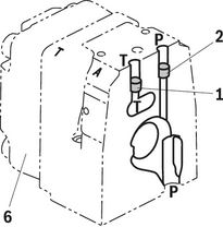
Size 16
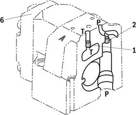
Size 25
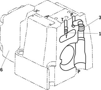
Size 27
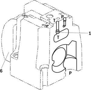
| Pilot oil supply | |
| External Internal | 2, 3 closed 2, 3 open |
| Pilot oil return | |
| External Internal | 1 closed 1 open |
| 1 | Plug screw M6 according to DIN 906, wrench size 3 - Pilot oil return |
| 2 | Plug screw M6 according to DIN 906, wrench size 3 - Pilot oil supply |
| 3 | Plug screw M12x1.5 according to DIN 906, SW6 - Pilot oil supply |
| 6 | Housing cover main stage (position transducer side) |
Version “XY"
External pilot oil supply, external pilot oil return
In this version, the pilot oil is supplied from a separate control circuit (external). The pilot oil return is not directed into channel T of the main valve, but is separately directed to the tank via port Y (external).
Version “PY”
Internal pilot oil supply, external pilot oil return
With this version, the pilot oil is supplied from channel P of the main valve (internally). The pilot oil return is not directed into channel T of the main valve, but is separately directed to the tank via port Y (external). In the subplate, port X is to be closed.
Version “PT”
Internal pilot oil supply; internal pilot oil return
With this version, the pilot oil is supplied from channel P of the main valve (internally). The pilot oil is directly returned to channel T of the main valve (internally). In the subplate, ports X and Y are to be closed.
Version “XT”
External pilot oil supply, internal pilot oil return
In this version, the pilot oil is supplied from a separate control circuit (external). The pilot oil is directly returned to channel T of the main valve (internally). In the subplate, port Y is to be closed.
Type code
| 01 | 02 | 03 | 04 | 05 | 06 | 07 | 08 | 09 | 10 | 11 | 12 | 13 | 14 | 15 | 16 | 17 | 18 | |||
| 4 | WRL | F | ‒ | 4X | / | 00 | / | 24 | D9 | * |
| 01 | 4 main ports | 4 |
| 02 | High-response directional valve, pilot operated | WRL |
| 03 | With integrated fieldbus | D |
| 04 | Size 10 | 10 |
| Size 16 | 16 | |
| Size 25 | 25 | |
| Size 27 | 27 | |
| 05 | Symbols; for the possible version, see "Symbols/Circuit diagrams" | |
| Rated flow (Δp = 5 bar/control edge) | ||
| 06 | Size 10 | |
| 60 l/min (only symbol E, E1-, W6-, W8-, V and V1-) | 60 | |
| 100 l/min | 100 | |
| Size 16 | ||
| 200 l/min (only symbol W6- and W8-) | 200 | |
| 250 l/min (only symbol E, E1-, V, V1- and Q3-) | 250 | |
| Size 25 | ||
| 350 l/min (only symbol W6- and W8-) | 350 1) | |
| 400 l/min (only symbol E, E1-, V, V1- and Q3-) | 400 | |
| Size 27 | ||
| 430 l/min (only symbol W6- and W8-) | 430 1) | |
| 600 l/min (only symbol E, E1-, V, V1- and Q3-) | 600 | |
| Flow characteristic | ||
| 07 | Linear | L |
| Linear with fine control range (only NG10; other sizes on request) | P | |
| Progressive with linear fine control range (only symbol Q3-) | M | |
| 08 | Without overlap jump (only symbols V, V1- and Q3-) | no code |
| With overlap jump (opening point 5% with covered valve; only symbols E, E1-, W6-, W8-) | J | |
| 09 | Component series 40 … 49 (40 … 49: unchanged installation and mounting dimensions) | 4X |
| Seal material (observe compatibility of seals with hydraulic fluid used, see "Technical data") | ||
| 10 | NBR seals | M |
| FKM seals | V | |
| Pilot oil flow | ||
| 11 | Pilot oil supply internal, pilot oil return internal | PT |
| Internal pilot oil supply, external pilot oil return | PY | |
| External pilot oil supply, internal pilot oil return | XT | |
| External pilot oil supply, external pilot oil return | XY | |
| Sandwich plate shut-off valve | ||
| 12 | Without shut-off valve | no code |
| With shut-off valve (Sandwich plate valve "Z4WE 6 E166-3X/EG24…", see data sheet 23193) | WL | |
| 13 | Without internal pressure sensors | 00 |
| 14 | Supply voltage 24 V | 24 |
| Ethernet interface | ||
| 15 | EtherNet/IP | E |
| PROFINET RT | N | |
| Sercos | S | |
| EtherCAT (Profil CANopen) | T | |
| POWERLINK (CANopen profile) | W | |
| VARAN | V | |
| Connector | ||
| 16 | Voltage supply, enable acknowledgement | D9 |
| Pressure sensor interface | ||
| 17 | Without interface | 0 |
| Analog interface for a maximum of 3 external pressure sensors (0 ... 10 V) | 5 | |
| 18 | Further details in the plain text | * |
| 1) | Higher rated flow upon request |
Technical data
general
| Type | 4WRLF | |||||
| Size | 10 | 16 | 25 | 27 | ||
| Component series | 4X | |||||
| Installation position | any | |||||
| Earth | kg | 9 | 12 | 19 | 21 | |
| Ambient temperature range | °C | -20 … +60 | ||||
| Storage temperature range | °C | +5 … +40 | ||||
| Maximum storage time 1) | yrs | 1 | ||||
| Sine test according to DIN EN 60068-2-6 | 10 ... 2000 Hz / maximum 10 g / 10 cycles / 3 axes | |||||
| Noise test according to DIN EN 60068-2-64 | 20 ... 2000 Hz / 10 gRMS / 30 g peak / 30 min. / 3 axes | |||||
| Transport shock according to DIN EN 60068-2-27 | 15 g / 11 ms / 3 axes | |||||
| Maximum relative humidity 2) | % | 95 | ||||
| Maximum surface temperature 3) | °C | 120 | ||||
| MTTFD values according to EN ISO 13849 4) | Hydraulic (category 1) | Years | 75 | |||
| Hydraulic and electric (category 3 and 4, without power supply unit) | Years | 70 | ||||
| 1) | If the storage conditions are observed; refer to the operating instructions 07600-B |
| 2) | No condensation |
| 3) | Individual operation |
| 4) | For further details, please refer to operating instructions 29391-B |
hydraulic
| Type | 4WRLF | ||||||
| Size | 10 | 16 | 25 | 27 | |||
| Maximum operating pressure | Port P | External pilot oil supply | bar | 350 | 270 | ||
| Anschluss A | bar | 350 | 270 | ||||
| Port B | bar | 350 | 270 | ||||
| Port P | Internal pilot oil supply | bar | 280 | 270 | |||
| Anschluss A | bar | 280 | 270 | ||||
| Port B | bar | 280 | 270 | ||||
| Port T | bar | 250 | 210 | ||||
| Port Y | bar | 250 | 210 | ||||
| Port X | bar | 280 | 270 | ||||
| Minimum pilot pressure | Pilot control valve | bar | 10 | ||||
| Maximum flow | l/min | 300 | 800 | 1250 | 1850 | ||
| Nominal flow 1) | l/min | 60 100 | 200 250 | 350 400 | 430 600 | ||
| Maximum leakage flow 2) | Symbol E, E1- | Main valve | l/min | 0.06 | 0.13 | 0.17 | |
| Main valve + pilot control valve | l/min | 0.14 | 0.28 | 0.42 | |||
| Symbol W6-, W8- | Main valve | l/min | 0.12 | 0.26 | 0.35 | ||
| Main valve + pilot control valve | l/min | 0.2 | 0.41 | 0.6 | |||
| Maximum zero flow 2) | Symbol Q3- | Main valve | l/min | 1.7 | 2.3 | 2.8 | 3.3 |
| Main valve + pilot control valve | l/min | 1.85 | 2.6 | 3.2 | 3.7 | ||
| Pilot flow 3) | Symbol E | l/min | 2.4 | 3.5 | 7.5 | ||
| Symbol W | l/min | 2.4 | 3.5 | 7.5 | |||
| Symbol V | l/min | 4.5 | 11.5 | 22 | |||
| Symbol Q3- | l/min | 4.5 | 11.5 | 22 | |||
| Flow unloading central position | Symbol W6- | A → T | l/min | 2.8 | 4 | 6 | |
| B → T | l/min | 2.8 | 4 | 6 | |||
| Symbol W8- | A → T | l/min | 2.8 | 4 | 6 | ||
| B → T | l/min | 1.4 | 2 | 3 | |||
| Hydraulic fluid | see table "Hydraulic fluid" | ||||||
| Hydraulic fluid temperature range | °C | -20 … +70 | |||||
| Viscosity range | Maximum admissible | mm²/s | 20 … 380 | ||||
| Recommended | mm²/s | 30 … 45 | |||||
| Maximum admissible degree of contamination of the hydraulic fluid, cleanliness class according to ISO 4406 (c) 4) | Class 18/16/13 | ||||||
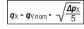
| 1) | Δp = 5 bar/control edge; flow with deviating Δpsee formula. |
| 2) | Inlet pressure 100 bar |
| 3) | At port X and Y with stepped input signal from 0 to 100 % (pilot pressure 100 bar) |
| 4) | The cleanliness classes specified for the components must be adhered to in hydraulic systems. Effective filtration prevents faults and simultaneously increases the life cycle of the components. |
| Hydraulic fluid | Classification | Suitable sealing materials | Standards | Data sheet | |
| Mineral oils | HL, HLP, HLPD, HVLP, HVLPD | NBR, FKM | DIN 51524 | 90220 | |
| Bio-degradable | Insoluble in water | HETG | NBR, FKM | ISO 15380 | 90221 |
| HEES | FKM | ||||
| Soluble in water | HEPG | FKM | ISO 15380 | ||
| Flame-resistant | Water-free | HFDU (glycol base) | FKM | ISO 12922 | 90222 |
| HFDU (ester base) | FKM | ||||
| HFDR | FKM | ||||
| Containing water | HFC (Fuchs: Hydrotherm 46M, Renosafe 500; | NBR | ISO 12922 | 90223 | |
| Important information on hydraulic fluids:
| |||||
static / dynamic
| Size | 10 | 16 | 25 | 27 | ||
| Hysteresis | % | < 0.1 | ||||
| Response sensitivity | % | < 0.05 | ||||
| Range of inversion | % | < 0.08 | ||||
| Manufacturing tolerance | % | ≤ 10 | ||||
| Actuating time for 0 … 100% at X =100 bar | Symbol E, E1-, W6-, W8- | ms | 40 | 60 | ||
| Switch-off behavior 1) | Symbol E, E1-, W6-, W8- | Pilot control valve in “fail-safe” position, main valve moves to spring-centered, overlapped central position | ||||
| Symbol V, V1- | Pilot control valve in “fail-safe” position, main valve moves to spring-centered “offset position” (approx. 6%, P-B/A-T) | |||||
| Symbol Q3- | Pilot control valve in “fail-safe” position, main valve moves to spring-centered "offset position" (P blocked, A/B to port T open) | |||||
| Temperature drift 2) | Zero shift < 0.25 %/10 °C | |||||
| Zero point calibration 3) | % | ± 1 | ||||
| 1) | After electric shut-off |
| 2) | Temperature range 20 °C ... 80 °C |
| 3) | ex works |
electrical, integrated electronics (OBE)
| Relative duty cycle 1) | 100 % | ||
| Protection class according to EN 60529 | IP65 (If a suitable and a correctly mounted mating connector are used.) | ||
| Power supply | Nominal voltage | VDC | 24 2) |
| Lower limit value | VDC | 18 | |
| Upper limit value | VDC | 36 | |
| Maximum residual ripple 3) | Vpp | 2.5 | |
| Current consumption | Maximum 4) | A | 2.5 |
| Impulse current | A | 4 | |
| Maximum power consumption | W | 40 | |
| AD/DA resolution 5) | Analog inputs | bits | 12 |
| Functional earth and screening | See connector pin assignment (CE-compliant installation), "Electrical connection" | ||
| Required fuse protection | 4, time-lag | ||
| Adjustment | Calibrated in the plant, see "characteristic curves" | ||
| Conformity | CE according to EMC directive 2014/30/EU tested according EN 61000-6-2 and EN 61000-6-3 | ||
| Parameterization interface | Ethernet | ||
| Scanning time 5) | Pressure and force controller (minimum) | ms | 0.5 |
| Booting time | s | < 15 | |
| 1) | Continuous operation |
| 2) | Supply voltage is used directly for sensor connection X8M (no internal voltage limitation). Voltage limit values must be observed directly at the connector of the valve (observe line length and cable cross-section). |
| 3) | Observe the absolute limit values of the supply voltage. |
| 4) | The maximum current consumption will increase when using the sensor inputs or the switching output according to the external load |
| 5) | Depending on valve and operating condition, see operating instructions 29391-B |
electrical, integrated electronics (OBE)
| Switching input Enable XH1 | Quantity |
| 1 |
| Low level | V | -3 ... +5 | |
| High level | V | 15 ... UB | |
| Current consumption at high level | mA | < 1 | |
| Reference potential |
| Pin 5 | |
| Switching output Enable acknowledgment XH1 | Quantity |
| 1 |
| Low level | V | 0 ... 3 | |
| High level | V | 15 ... UB | |
| Current carrying capacity | mA | 50 (short-circuit-proof) | |
| Signal delay time | ms | 0,2 … 210 1) | |
| Reference potential |
| GND | |
| Analog sensor X2N | Quantity (voltage inputs) |
| 3 2) |
| Power supply | V | 24 (corresponding to supply voltage applied to XH2) | |
| Maximum supply current | mA | 50 | |
| AD resolution | bit | 12 | |
| Voltage inputs | |||
| Measurement range | V | 0 ... +10 | |
| Input resistance | kΩ | 100 +10 % | |
| Temperature drift |
| < 15 mV / 10 K | |
| 1) | Depending on valve and operating condition, see operating instructions 29391-B |
| 2) | Only version "5" |
(For applications outside these values, please consult us!)
Diagrams/characteristic curves
(measured with HLP46, ϑOil = 40 ±5 °C)
Pressure amplification
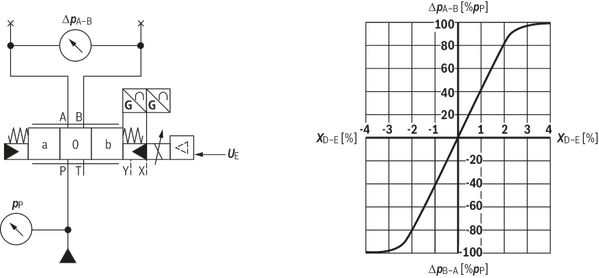
Flow characteristic "L"
Flow/signal function
Symbol V, V1-
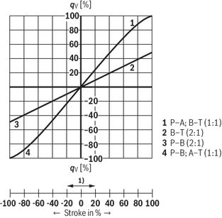
| 1) | Step compensation (opening at 5%) |
Flow/signal function
Symbol E, E1-, W6-, W8-
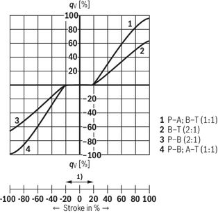
| 1) | Step compensation (opening at 5%) |
Flow characteristic "P"
Flow/signal function
Symbol V, V1-
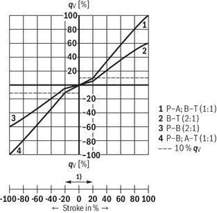
| 1) | Step compensation (opening at 5%) |
Flow/signal function
Symbol E, E1-, W6-, W8-
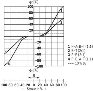
| 1) | Step compensation (opening at 5%) |
Flow characteristic "M"
Symbol Q3, version "100"

Symbol Q3, version "250"

Symbol Q3, version "400"

Symbol Q3, version "600"

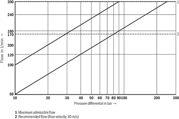
Size 10
Transition function with stepped electric input signals
Symbols V and Q3-
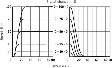
- Pilot control valve, port X = 100 bar
- Main valve, port P = 10 bar
Frequency response
Symbols V and Q3-
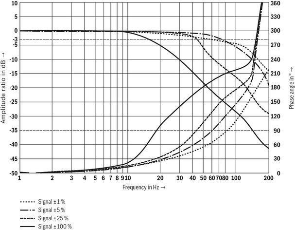
Flow/load function with maximum valve opening (tolerance ±10 %)
Size 16
Transition function with stepped electric input signals
Symbol V
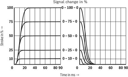
- Pilot control valve, port X = 100 bar
- Main valve, port P = 10 bar
Frequency response
Symbol V
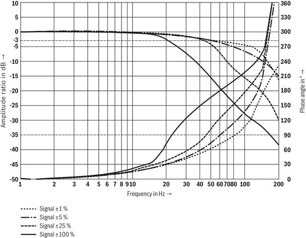
Flow/load function with maximum valve opening (tolerance ±10 %)
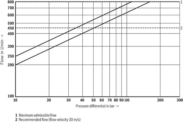
Size 25
Transition function with stepped electric input signals
Symbol V
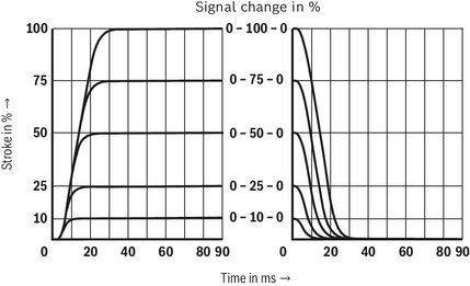
- Pilot control valve, port X = 100 bar
- Main valve, port P = 10 bar
Frequency response
Symbol V
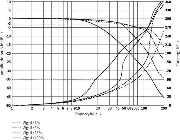
Flow/load function with maximum valve opening (tolerance ±10 %)
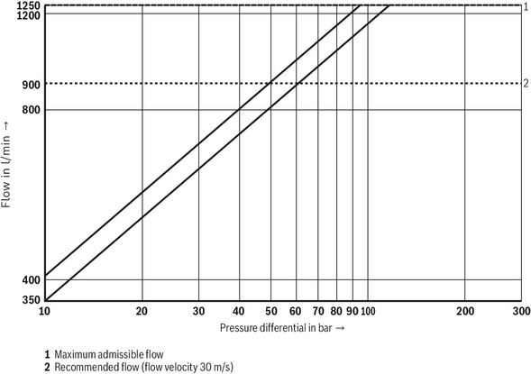
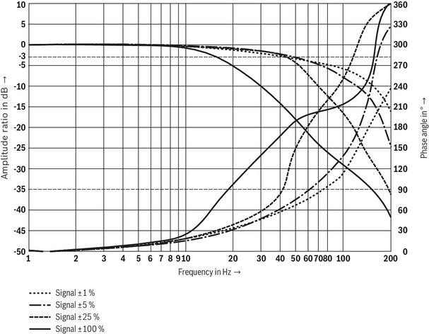
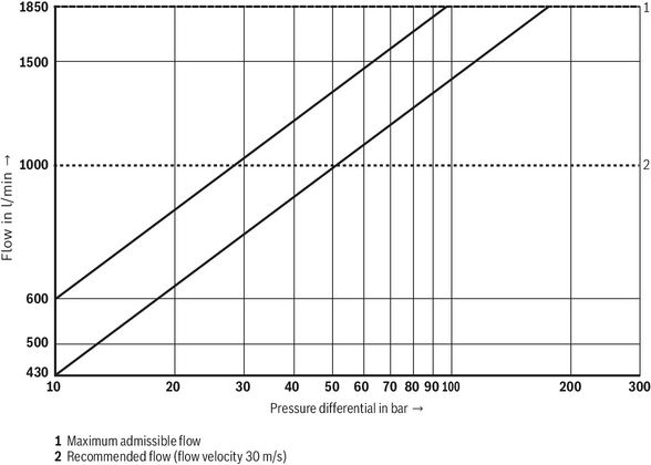
Size 27
Transition function with stepped electric input signals
Symbol V
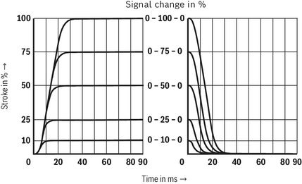
- Pilot control valve, port X = 100 bar
- Main valve, port P = 10 bar
Frequency response
Symbol V
Flow/load function with maximum valve opening (tolerance ±10 %)
Symbols/Circuit diagrams
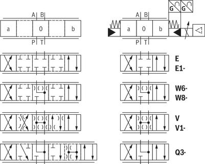
| Symbol E1-, V1- and W8-: | |
| P → A: qv max P → B: qv/2 | B → T: qv/2 A → T: qv max |
| Version | simple | Detailed |
| "XY" | 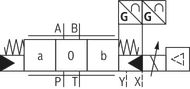 | 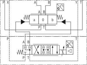 |
| "PY" | 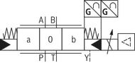 | |
| "PT" | 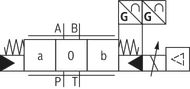 | |
| "XT" | 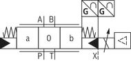 |
Notices:
- Representation according to ISO 1219-1. Hydraulic interim positions are shown by dashes.
- For information on the switch-off behavior, refer to "technical data".
- Symbols V and V1- are not suitable for use in safety applications (no overlap).
Electrical connection
Block diagram / controller function block
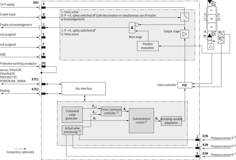
| 1) | Only version "5" |
| 2) | Not with "VARAN" |
Detailed description of the safety function:
After the signal at the enable input has been removed, the output stage, and thus the solenoid of the valve, are internally separated from the available supply voltage. The enable acknowledgment will only be activated after the safe valve spool position has been achieved.
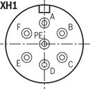
Connector pin assignment XH1, 6-pole + PE according to DIN 43563
| Pin | Assignment of interface D9 |
| A | 24 VDC supply voltage 1) |
| B | GND |
| C | Enable acknowledgment 24 VDC (Imax 50 mA; high ≥ 15 V; low < 2 V) 2) |
| D | Enable input 24 VDC (high ≥ 15 V; low < 2 V) |
| E | Not assigned |
| F | Not assigned |
| PE | Functional ground (directly connected to the valve housing) |
| 1) | A load increases the current consumption on pin A |
| 2) | Enable acknowledgement is issued only if the valve has safely switched off according to EN 13849-1, see operating instructions 29391-B. |
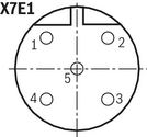
Connector pin assignment: M12 x 1, 4-pole, coding D, socket (for Ethernet interfaces "X7E1" and "X7E2")
| Pin | Assignment |
| 1 | TxD + |
| 2 | RxD + |
| 3 | TxD - |
| 4 | RxD - |
| 5 | Not assigned |
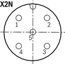
Analog configurable sensor interfaces, connection "X2N" (coding A), M12, 5-pole, socket
| Pin | Assignment |
| 1 | +24 V voltage output |
| 2 | Analog sensor input 2 (0 ... 10 V) |
| 3 | GND |
| 4 | Analog sensor input 4 (0 ... 10 V) |
| 5 | Analog sensor input 3 (0 ... 10 V) |
| 1) | Only version "5" |
Notices:
- Reference potential for all signals : GND
- We recommend connecting the shields on both sides via the metal housings of the plug-in connectors.
LED displays
| LED | Interface | Sercos | EtherNet/IP | EtherCAT | PROFINET RT | POWERLINK | VARAN |
| MS | Electronic module | Module Status | Module Status | Module Status | Module Status | Module Status | Module Status |
| NS | S | Network status and others | Network status and others | Network status and others | Status/Error | Network status and others | |
| L1 | X7E1 | Link and others | Link and others | Link/Activity | Link and others | Link/Data Activity | Link and others |
| S1 | Activity and others | Activity and others | not used | Activity and others | not used | Activity and others | |
| L2 | X7E2 | Link and others | Link and others | Link/Activity | Link and others | Link/Data Activity | not used |
| S2 | Activity and others | Activity and others | not used | Activity and others | not used | not used | |
| PWR | XH1 | Power | Power | Power | Power | Power | Power |
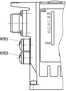
Displays of the Status LEDs
| Module status (LED MS) | Display status |
| Off | No voltage supply |
| Green-red, flashing | Initialization |
| Green, flashing | Drive ready for operation |
| Green | Drive active |
| Orange, flashing | Warning |
| Red, flashing | Error |
| Green, rapidly flashing | Firmware must be loaded |
| Power LED (LED PWR) | Display status |
| Off | No voltage supply |
| Green | Operation |
| Link-LED (LED L1) | Display status |
| Permanently lit | Cable plugged in, connection established |
| Activity-LED (LED S1) | Display status |
| Flashing | Data sent/received |
Notices:
- For the connection to the M12 sockets, we recommend using self-locking mating connectors.
- Module status LED MS relates to the electronics module.
- The network status LED NS indicates the status of the control communication, see application description 30338-FK.
- LEDs L1, S1, L2 and S2 relate to interfaces "X7E1" and "X7E2"
- For a detailed description of the diagnosis LEDs, please refer to the functional description "Rexroth HydraulicDrive HDx".
- Function is only available after start-up of the electronics.
Dimensions
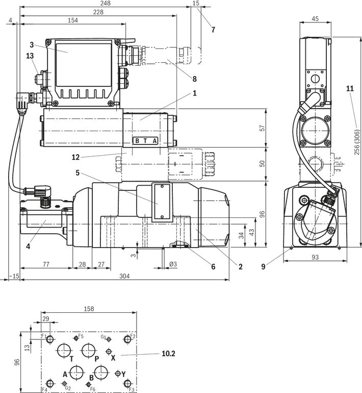
Size 10
Dimensions in mm
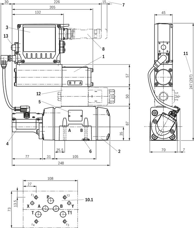
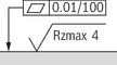 Required surface quality of the valve contact surface |
| 1 | Pilot control valve |
| 2 | Main valve |
| 3 | Integrated electronics (OBE) |
| 4 | Inductive position transducer (main valve) |
| 5 | Name plate |
| 6 | Identical seal rings for ports A, B, P, T Identical seal rings for ports X and Y |
| 7 | Space required to remove the mating connector |
| 8 | Mating connectors, separate order, see "Accessories" |
| 10 | Machined valve contact surface; porting pattern according to ISO 4401-05-05-0-05 |
| 11 | Dimension () with version "WL" |
| 12 | Shut-off valve, optional (sandwich plate valve "Z4WE 6 E166-3X/EG24…", see data sheet 23193) |
| 13 | Port X2N (only version "5") |
Notice:
The dimensions are nominal dimensions which are subject to tolerances.
Valve mounting screws (separate order)
| Size | Quantity | Hexagon socket head cap screws | Material number |
| 10 | 4 | ISO 4762 - M6 x 45 - 10.9-CM-Fe-ZnNi-5-Cn-T0-H-B Tightening torque MA = 13.5 Nm ±10 % | R913043777 |
| or | |||
| 4 | ISO 4762 - M6 x 45 - 10.9 Tightening torque MA = 15.5 Nm ±10 % | Not included in the Rexroth delivery range | |
Notice:
The tightening torque of the hexagon socket head cap screws refers to the maximum operating pressure.
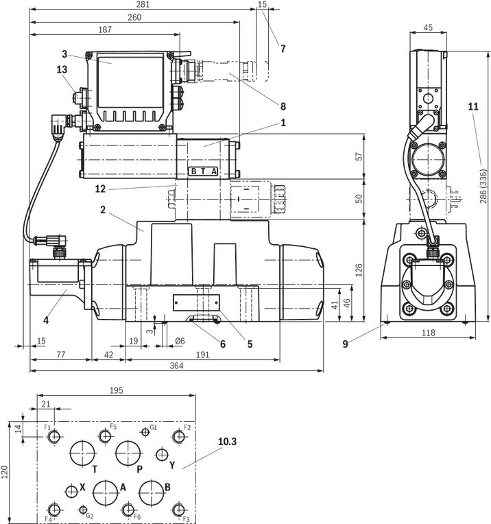
Size 16
Dimensions in mm
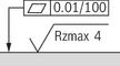 Required surface quality of the valve contact surface |
| 1 | Pilot control valve |
| 2 | Main valve |
| 3 | Integrated electronics (OBE) |
| 4 | Inductive position transducer (main valve) |
| 5 | Name plate |
| 6 | Identical seal rings for ports A, B, P, T Identical seal rings for ports X and Y |
| 7 | Space required to remove the mating connector |
| 8 | Mating connectors, separate order, see "Accessories" |
| 9 | Locking pin |
| 10 | Machined valve contact surface; Porting pattern according to ISO 4401-07-07-0-05 |
| 11 | Dimension () with version "WL" |
| 12 | Shut-off valve, optional (sandwich plate valve "Z4WE 6 E166-3X/EG24…", see data sheet 23193) |
| 13 | Port X2N (only version "5") |
Notice:
The dimensions are nominal dimensions which are subject to tolerances.
| Size | Quantity | Hexagon socket head cap screws | Material number |
| 16 | 2 | ISO 4762 - M6 x 60 - 10.9-CM-Fe-ZnNi-5-Cn-T0-H-B Tightening torque MA = 12.2 Nm ±10 % | R913043410 |
| 4 | ISO 4762 - M10 x 60 - 10.9-CM-Fe-ZnNi-5-Cn-T0-H-B Tightening torque MA = 58 Nm ±20 % | R913014770 | |
| or | |||
| 2 | ISO 4762 - M6 x 60 - 10.9 Tightening torque MA = 15.5 Nm ±10 % | Not included in the Rexroth delivery range | |
| 4 | ISO 4762 - M10 x 60 - 10.9 Tightening torque MA = 75 Nm ±20 % | ||
Notice:
The tightening torque of the hexagon socket head cap screws refers to the maximum operating pressure.
Size 25
Dimensions in mm
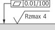 Required surface quality of the valve contact surface |
| 1 | Pilot control valve |
| 2 | Main valve |
| 3 | Integrated electronics (OBE) |
| 4 | Inductive position transducer (main valve) |
| 5 | Name plate |
| 6 | Identical seal rings for ports A, B, P, T Identical seal rings for ports X and Y |
| 7 | Space required to remove the mating connector |
| 8 | Mating connectors, separate order, see "Accessories" |
| 9 | Locking pin |
| 10 | Machined valve contact surface; Porting pattern according to ISO 4401-08-08-0-05 |
| 11 | Dimension () with version "WL" |
| 12 | Shut-off valve, optional (sandwich plate valve "Z4WE 6 E166-3X/EG24…", see data sheet 23193) |
| 13 | Port X2N (only version "5") |
Notice:
The dimensions are nominal dimensions which are subject to tolerances.
Valve mounting screws (separate order)
| Size | Quantity | Hexagon socket head cap screws | Material number |
| 25, 27 | 6 | ISO 4762 - M12 x 60 - 10.9-CM-Fe-ZnNi-5-Cn-T0-H-B Tightening torque MA = 100 Nm ±20 % | R913015613 |
| or | |||
| 6 | ISO 4762 - M12 x 60 - 10.9 Tightening torque MA = 130 Nm ±20 % | Not included in the Rexroth delivery range | |
Notice:
The tightening torque of the hexagon socket head cap screws refers to the maximum operating pressure.
Size 27
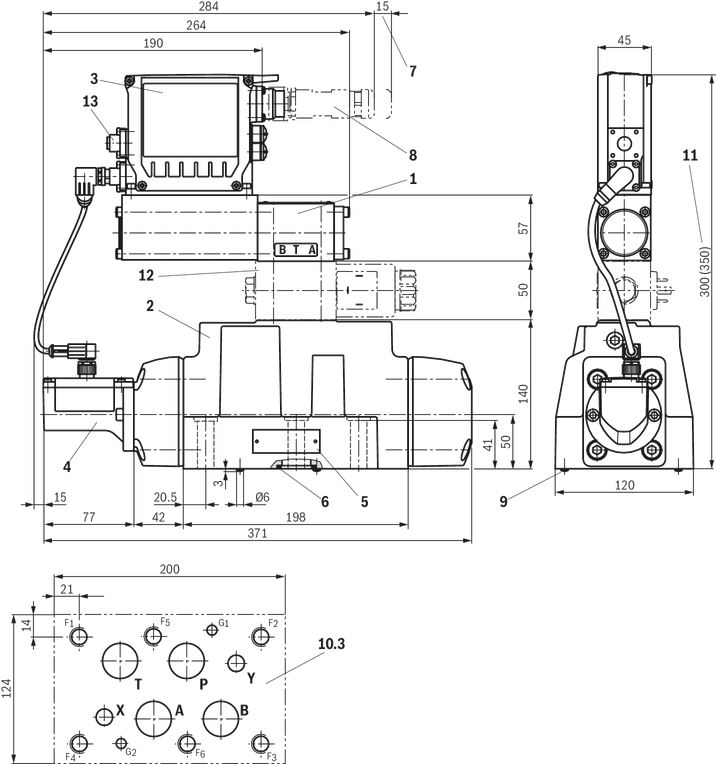
Dimensions in mm
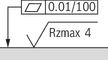 Required surface quality of the valve contact surface |
| 1 | Pilot control valve |
| 2 | Main valve |
| 3 | Integrated electronics (OBE) |
| 4 | Inductive position transducer (main valve) |
| 5 | Name plate |
| 6 | Identical seal rings for ports A, B, P, T Identical seal rings for ports X and Y |
| 7 | Space required to remove the mating connector |
| 8 | Mating connectors, separate order, see "Accessories" |
| 9 | Locking pin |
| 10 | Machined valve contact surface; Porting pattern according to ISO 4401-08-08-0-05 |
| 11 | Dimension () with version "WL" |
| 12 | Shut-off valve, optional (sandwich plate valve "Z4WE 6 E166-3X/EG24…", see data sheet 23193) |
| 13 | Port X2N (only version "5") |
Notice:
The dimensions are nominal dimensions which are subject to tolerances.
Valve mounting screws (separate order)
| Size | Quantity | Hexagon socket head cap screws | Material number |
| 25, 27 | 6 | ISO 4762 - M12 x 60 - 10.9-CM-Fe-ZnNi-5-Cn-T0-H-B Tightening torque MA = 100 Nm ±20 % | R913015613 |
| or | |||
| 6 | ISO 4762 - M12 x 60 - 10.9 Tightening torque MA = 130 Nm ±20 % | Not included in the Rexroth delivery range | |
Notice:
The tightening torque of the hexagon socket head cap screws refers to the maximum operating pressure.
Subplates (separate order) with porting pattern according to ISO 4401, see data sheet 45100.
Project planning information
Project planning and maintenance instructions
- The supply voltage must be permanently connected, as otherwise bus communication is not possible.
- If electro-magnetic interference is to be anticipated, suitable measures must be taken to ensure the function (depending on the application, e.g. shielding, filtration).
- The devices have been tested in the plant and are supplied with default settings.
- Only complete devices can be repaired. Repaired devices are returned with default settings. User-specific settings will not be applied. The machine end-user will have to retransfer the corresponding user parameters.
Accessories
Protective cap M12
Material number R901075563

Mating connectors for valves with round connector, 6-pole + PE
7P Z31
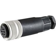
Mating connectors for valves with round connector, 6-pole + PE
7P Z31
- For valves with round connector according to EN 175201-804, 6-pole + PE as well as 6-pole, compatible with VG 95328
Mating connectors for valves with round connector, 6-pole + PE, shielded, with assembled connection line
7P Z31 +
Mating connectors for valves with round connector, 6-pole + PE, shielded, with assembled connection line
7P Z31 +
- For valves with round connector according to EN 175201-804, 6-pole + PE as well as 6-pole, compatible with VG 95328
Downloads


Цена по запросу
Цена по запросу
Нет отзывов об этом товаре.