
Доступно к заказу
Цена по запросу
И выбери подходящего.
Description
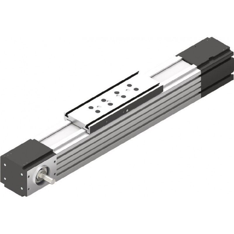
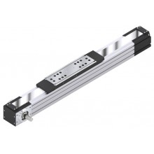
- Linear Modules with Cam Roller Guide and toothed belt drive
- High performance toothed belt (AT profile) for high travel speeds of up to 10 m/s
- Extremely compact aluminum profile with integrated Rexroth cam roller guide with inserted cam rollers (cam rollers, set to zero-clearance via eccentric shafts)
- With planetary gearbox with various gear ratios and versions for optimizing external load to motor inertia.
- Realization of greater lengths of up to 10000 mm
Features
- Protection of the guide components by toothed belt
- Aluminum carriages with T-grooves and centering holes and central lubrication point (oil lubrication!)
- Repeatability of up to ± 0.05 mm
- Servo motor with multi-turn absolute encoder both with and without holding brake
- The external load can be optimally adapted to the drive motor inertia thanks to the different speed reductions. The planetary gearbox can be integrated in a belt drive pulley or mounted as a gear reducer. This results in a high-dynamic drive.
- The toothed belt provides a cover
- Centering holes also in main body profile for simple combination with other linear motion systems and connection elements
- Standard with integrated solenoid switch for magnetic field sensors
- Extensive accessories for connection and clamping elements and connecting shafts
- Nameplate with parameters for easy start-up
Product description
Rexroth linear modules are precise, ready-to-mount guide systems that combine high-performance characteristics with compact dimensions. Rexroth provides a favorable price/performance ratio and fast delivery times.
Linear modules can be delivered complete with motors, controllers and control system.
Structural design
- Ready-to-install linear modules in any length up to Lmax
- Realization of greater lengths of up to 10000 mm
- Extremely compact aluminum profile with integrated Rexroth cam roller guide with inserted cam rollers (cam rollers, set to zero-clearance via eccentric shafts)
- Aluminum carriages with T-grooves and centering holes and central lubrication point (oil lubrication!)
- High-performance toothed belt (AT profile) for high drive torques with simultaneously high rigidity
- Protection of the guide components by toothed belt
- Version available without drive (support axle)
Attachments
- Planetary gearbox with various gear ratios
- Motor attachment kits according to customer specification
- Servomotor
- Magnetic field sensors for easy assembly directly on the profile frame
- Switches proximity or mechanical, cable channel
Attachments (range of accessory products)
- Sensors and extension cables
- Switches (proximity or mechanical)
- Cam switch
- Socket and plug
- Aluminum profile cable channel
- Clamping fixtures and sliding blocks
- Connecting shafts
- Connecting technology for linear motion systems
Caution: Linear modules with cam roller guide to be lubricated with oil only!
Structure and attachments
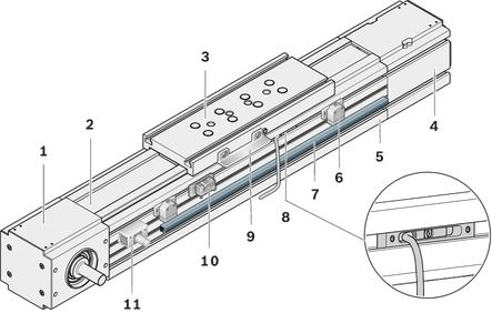
Structural design
1 End head (drive side)
2 Toothed belt
3 Carriage
4 End head (clamping side)
5 Main body
Attachments:
6 Mechanical switch
7 Cable channel
8 Magnetic field sensor
9 Switch bracket
10 Proximity switch
11 Socket/plug
Models
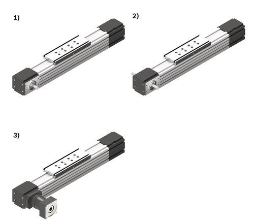
| 1) | Journal for motor attachment right or left |
| 2) | Journal for motor attachment on both sides |
| 3) | With gear reducer (motor mounting via clamping hub) |
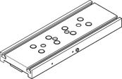
Carriage variants
Carriage (TT) with T-grooves
Technical data
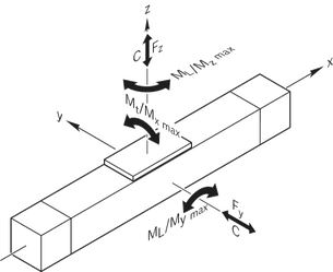
Maximum values for each size
| Size | MLR-080 | MLR-110 | |
| Cy | N | 17150 | 31000 |
| Cz | N | 10050 | 18200 |
| Mt | Nm | 226 | 629 |
| ML | Nm | 316 | 1121 |
| Mx max | Nm | 35 | 49 |
| My max | Nm | 158 | 302 |
| Mz max | Nm | 158 | 302 |
| Fy max | N | 2500 | 8000 |
| Fz1 max | N | 1500 | 4800 |
| Fz2 max | N | 1500 | 4800 |
| Lmax | mm | 10000 | |
| amax | m/s² | 50 | |
| vmax | m/s | 10 | |
| Maximum values depends on the selected configuration. |
Legend
| Symbol | Description | Unit |
| Cy | Dynamic load capacity in y-direction | N |
| Cz | Dynamic load capacity in z-direction | N |
| Mt | Dynamic torsional moment load capacity | Nm |
| ML | Dynamic longitudinal moment load capacity | Nm |
| Mx max | Dynamic torsional moment about the x-axis | Nm |
| My max | Dynamic torsional moment about the y-axis | Nm |
| Mz max | Dynamic torsional moment about the z-axis | Nm |
| Fy max | Maximum dynamic load in y-direction | N |
| Fz1 max | Maximum dynamic load in z-direction | N |
| Fz2 max | Maximum dynamic load in z-direction | N |
| Lmax | Maximum length | mm |
| amax | Maximum acceleration travel | m/s2 |
| vmax | Maximum permissible speed | m/s |
Mounting
Mounting
General information
The linear modules are mounted using various fastening elements:
- Clamping fixtures
- Sliding blocks for size -110 and up
- Square nuts
- Spring nuts
- Screws for T-slots as per DIN 787 (no picture).
Length depends on base.
When mounting Linear Modules, please note the maximum tightening torques listed in the table.
Mounting with clamping fixtures
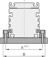
Mounting with sliding blocks
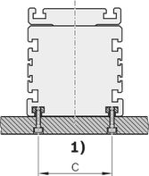
| 1) | 85 (size .. -110) 120 (size -165) |
| Size | A | B | C |
| (mm) | (mm) | (mm) | |
| -040 | 52,2 | 65,5 | - |
| -065 | 81,0 | 95,0 | - |
| -080 | 96,0 | 110,0 | - |
| -110 | 132,0 | 150,0 | 85,0 |
| -140 | 167,0 | 193,0 | 105,0 |
| -145 | 172,0 | 198,0 | 78,0 |
| -165 | 192,0 | 218,0 | 120,0 |
Do not support the linear module on end enclosures, end blocks or on end plates!
The frame is the load-bearing part!
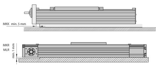
Tightening torques of fastening screws
with friction factor 0.125 strength class 8.8
 | 8.8 | M4 | M5 | M6 | M8 | M10 | M12 |
 | (Nm) | 2,7 | 5,5 | 9,5 | 23 | 46 | 80 |
Switching system overview
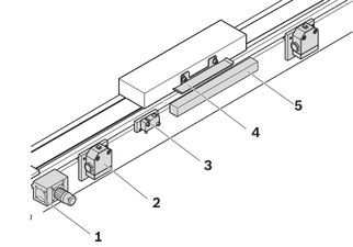
1 Socket and plug
2 Mechanical switch with attachments
3 Proximity switch
4 Switching cam
5 Mounting duct/cable duct
Switch mounting MKK/MKR/MLR-xxx-NN-x
MKK/MKR/MLR-xxx-NN-x
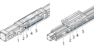
Proximity sensors, mechanical switches and accessories (MKK/MKR/MLR)
Mounting instructions:
The mechanical switches, the proximity sensors and the socket with plug and cable channel are fastened with attachments in T-grooves of the main body. Switch activation is carried out by a switch bracket on the carriage.
| Position | Name | Size -065/-080/-140 /-145-NN-3 | -110-NN-3 | -165-NN-2 |
| Material number | ||||
| 1 | Socket-plug | R117500153 | ||
| 2 | Mechanical switch | see accessories | ||
| Mechanical switch with attachments | R117500151 | |||
| 3 | Proximity sensor | see accessories | ||
| - Attachment parts without sensor | R117500152 | R117520152 | R117500152 | |
| 4 | Switching angle | R117500149 | R117500150 | |
| 5 | Cable duct | R039662017 | ||
| These switching versions can only be ordered with these material numbers. |
| Proximity sensor with additional attachment for | Proximity sensor with additional attachment for | Mechanical switch with attachment for |
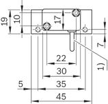 | 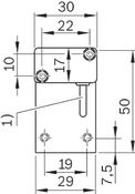 | 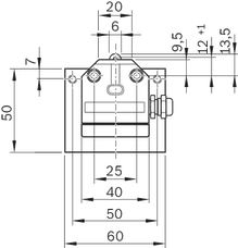 |
| 1) | Cable length: 3 m |
Socket and plug, cable duct
Attach the socket to the side with the most switches. The socket and plug are not pre-wired. The variable sliding attachment allows switching positions to be optimized during start-up. The plug can be mounted in three directions.
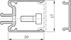
Cable duct
The cable duct is fastened in the T-slots on the side of the frame. Fastening screws widen the profile and ensure that the cable duct is securely mounted.
See the illustration for the position of the slot.
The cable duct will accommodate up to two cables for mechanical switches and three cables for proximity switches.
Fastening screws and cable grommets are included.
Mounting examples of switches
Determination of the switching position
Switching distance: The switching distance is the distance between the carriage center (TM) and the zero point (0) when a switch is actuated (indicated in mm). Example of a mechanical limit switch (assuming the zero point is at L/2):
Maximum switching distance = 0.5 x (max. travel distance) – excess travel = 0.5 x effective stroke
For safe operation of the linear module the excess travel must be greater than the braking path.
For MKR... and MLR...: The acceleration travel sa can be assumed as the reference value for the braking distance.
For MKK...: In most cases, the following is sufficient as a guideline value for the excess travel (braking path): Excess travel = 2 x screw lead P.
Note the smallest possible switching distance (determined by attachments):
mechanical-mechanical = 60 mm; mechanical-proximity = 45 mm; proximity-proximity = 28 mm.
for MKR-145: mechanical-mechanical = 62 mm; mechanical-proximity = 49 mm; proximity-proximity = 35 mm
The switches as well as socket with plug are fixed in the upper T-slots of the frame and actuated by a switch tab on the carriage.
Mounting side of the switches:
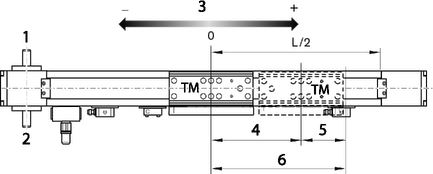
| 1) | links (L) |
| 2) | right (R) |
| 3) | Direction of travel |
| 4) | 0.5 x stroke |
| 5) | Excess travel |
| 6) | 0.5 x max. travel path |
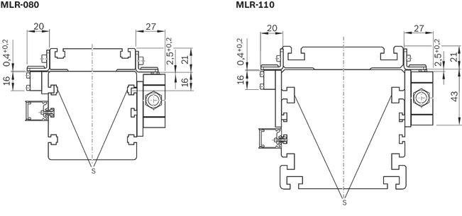
Switch connection
S = Slot for sensor holder MLR-xxx-NN-3
Accessories
Clamping fixtures for Linear Modules
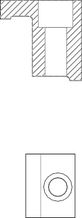
Clamping fixtures for Linear Modules
Sliding blocks and springs for Linear Modules
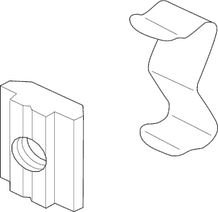
Sliding blocks and springs for Linear Modules
Anchor strips for Linear Modules

Anchor strips for Linear Modules
Centering rings for Linear Modules
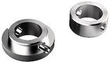
Centering rings for Linear Modules
Square nuts for Linear Modules
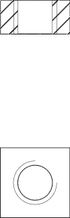
Square nuts for Linear Modules
Cable duct
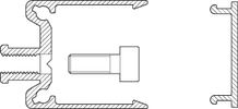
Cable duct
Frequency meter
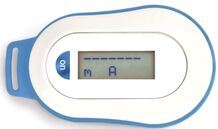
Frequency meter
Proximity sensor with free line end
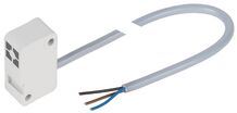
Proximity sensor with free line end
Proximity sensor with M8x1 plug
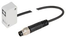
Proximity sensor with M8x1 plug
Additional components for inductive sensor
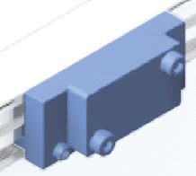
Additional components for inductive sensor
Magnetic sensors
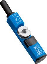
Magnetic sensors
Mechanical switch
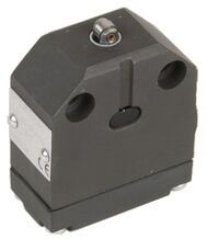
Mechanical switch
Mechanical switch with M8x1 plug
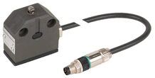
Mechanical switch with M8x1 plug
Additional components for mechanical switch
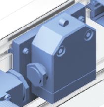
Additional components for mechanical switch
Adapter
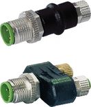
Adapter
Socket and plug
R117500153
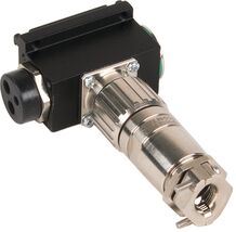
Socket and plug
R117500153
Switching angle
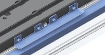
Switching angle
Nozzle pipe
R3455 031 06

Nozzle pipe
R3455 031 06
- For manual grease guns
- For the lubrication of funnel-type and ball-type lube nipples
Safety Instructions
Required and supplementary documentation
For further instructions and information, please refer to the documentation for this product.
You can find PDF files of these documents on the Internet at www.boschrexroth.com/mediadirectory.
We would also be happy to send you the documents that you want.
If you are unsure about using this product, please contact Bosch Rexroth.
Ordering codes
Order overview
| Size | Part number | Short product name | CAD data | Buy |
| MLR-080 | R114816013 | MLR-080-NN-3 | ||
| MLR-110 | R114826013 | MLR-110-NN-3 |
Explanation of short product name
| Linear Module MLR example | MLR-110-NN-3 | |
| System | M = | Linearmodule |
| Linear guide | L = | Cam Roller Guide |
| Drive | R = | Toothed belt drive |
| Size | 110 = | 080/110 |
| Version | NN = | Normal version |
| Generation | 3 = | Product generation 3 |
Downloads


Нет отзывов об этом товаре.