
Доступно к заказу
Цена по запросу
И выбери подходящего.
Description
- Rexroth connection dimensions
- With seals
- Preload class: C1, C2, C3
- Tolerance grade: T3 (for sizes as per the product overview for screws, see General Technical Notes and Information "Product description"), T5, T7
Product description
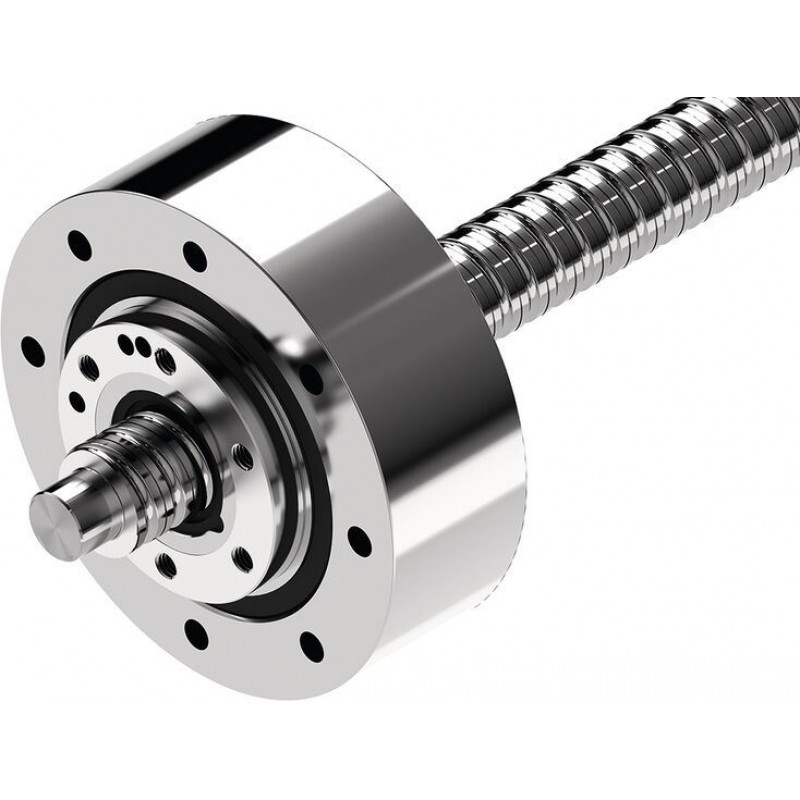
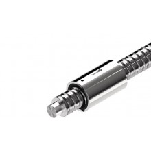
Driven flanged single nut FAR-B-S
The assembly consists of:
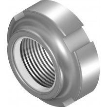
nut, angular-contact thrust ball bearing, and slotted nut NMZ
Fundamental advantages of systems with driven nuts
Moment of inertia
In the case of long screws, the screw does not have to be rotated in the acceleration phase, only the nut. The mass moment of inertia of the screw is not therefore critical. The moment of inertia of the nut is comparatively low and it is no longer dependent on the required stroke.
Dynamics
The intricate end bearing designs required for high dynamics, for example, fixed bearing on both ends with angular-contact ball bearings, are no longer necessary.
Screw extenders
Since the screw is stationary, relatively little effort is needed to stretch the screw:
- Increase in permissible axial loading (buckling load); not limited by end bearings
- Compensation of temperature influences
- Increase in overall rigidity
Design and manufacturing tolerances
The use of nuts with a high level of axial and radial runout precision minimizes the induced screw vibration. All functional components are supplied from a single source. In-house designs are no longer needed.
Liquid cooling
Improved cooling can easily be provided using a hollow-bored screw: the stationary screw can be cooled with comparatively little effort. Controlled cooling virtually eliminates changes in length due to temperature fluctuations.
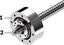
1) Driven nut FAR
2) Ball screw assemblies BSA screw
Product overview
Technical data
Technical data for nuts
| Size | C | C0 | Mass | JFAR | MRb | nmax |
| d0 x P x Dw - i | N | N | kg | kg·m² | Nm | rpm |
| 32 x 10R x 3,969 - 5 | 38000 1) | 58300 1) 2) | 5.8 | 0225 | 1 | 3000 3) |
| 32 x 20R x 3,969 - 3 | 23600 1) | 33700 1) 2) | 5.9 | 0229 | ||
| 32 x 32R x 3,969 - 3 | 23400 1) | 34000 1) 2) | 6.3 | 0251 | ||
| 40 x 10R x 6 - 5 | 73400 1) | 109300 1) 2) | 7.3 | 0427 | 1.2 | 2800 3) |
| 40 x 20R x 6 - 3 | 45500 1) | 62800 1) 2) | 7.5 | 0439 | ||
| 40 x 40R x 6 - 3 | 44400 1) | 62300 1) 2) | 8.4 | 0507 | ||
| 50 x 10R x 6 - 6 | 95600 1) | 166500 1) 2) | 8.3 | 0676 | 1.4 | 2700 3) |
| 50 x 20R x 6,5 - 5 | 90800 1) | 149700 1) 2) | 9.1 | 076 | ||
| 50 x 40R x 6,5 - 3 | 55800 1) | 85900 1) 2) | 9.5 | 0798 | ||
| 63 x 10R x 6 - 6 | 106600 1) | 214300 1) 2) | 12.8 | 0.0139 | 2.3 | 2300 3) |
| 63 x 20R x 6,5 - 5 | 100700 1) | 190300 1) 2) | 13.5 | 0.01564 | ||
| 63 x 40R x 6,5 - 3 | 64100 1) | 114100 1) 2) | 13.9 | 0.01616 |
| 1) | Load ratings calculated according to DIN ISO 3408-5 |
| 2) | The load ratings are valid for tolerance grades T3 and T5 only. For other tolerance grades, please take into account the correction factor fac (see General Technical Notes and Information "Technical Data", Technical Notes). |
| 3) | Limited by the max. speed of the bearing. Bearing pretensioned without external operating load. Duty cycle 25%; max. steady-state temp. +50°C |
Operating conditions
| Size | Admissible operating temperature (min ... max) 1) | Admissible storage temperature (min ... max) |
| d0 x P x Dw - i | ||
| 32 x 10R x 3,969 - 5 | -10 °C ... +80 °C | -15 °C ... +80 °C |
| 32 x 20R x 3,969 - 3 | ||
| 32 x 32R x 3,969 - 3 | ||
| 40 x 10R x 6 - 5 | ||
| 40 x 20R x 6 - 3 | ||
| 40 x 40R x 6 - 3 | ||
| 50 x 10R x 6 - 6 | ||
| 50 x 20R x 6,5 - 5 | ||
| 50 x 40R x 6,5 - 3 | ||
| 63 x 10R x 6 - 6 | ||
| 63 x 20R x 6,5 - 5 | ||
| 63 x 40R x 6,5 - 3 |
| 1) | Ball screw assemblies are suitable for continuous operation at temperatures up to 80 °C with temporary peaks of 100 °C (measurements taken on the outer shell of the nut). |
FAR rigidities
| FAR size | Size | Rs pro Meter 1) | Rfb | Rca | ||
| d0 x P x Dw - i | Preload class C1 | Preload class C2 | Preload class C3 | |||
| N/μm | N/μm | N/μm | N/μm | N/μm | ||
| 32 | 32 x 10R x 3,969 - 5 | 141 | 860 | 320 | 350 | 380 |
| 32 x 20R x 3,969 - 3 | 220 | 250 | 280 | |||
| 32 x 32R x 3,969 - 3 | 240 | 270 | ||||
| 40 | 40 x 10R x 6 - 5 | 211 | 950 | 390 | 420 | 450 |
| 40 x 20R x 6 - 3 | 270 | 300 | 330 | |||
| 40 x 40R x 6 - 3 | 290 | |||||
| 50 | 50 x 10R x 6 - 6 | 345 | 1050 | 490 | 520 | 560 |
| 50 x 20R x 6,5 - 5 | 340 | 450 | 480 | 530 | ||
| 50 x 40R x 6,5 - 3 | 320 | 350 | 390 | |||
| 63 | 63 x 10R x 6 - 6 | 569 | 1150 | 560 | 600 | 640 |
| 63 x 20R x 6,5 - 5 | 563 | 520 | 560 | 610 | ||
| 63 x 40R x 6,5 - 3 | 390 | 420 | 460 | |||
| 1) | Per meter. |
Legend
| Symbol | Description | Unit |
| d0 | Nominal diameter | mm |
| P | Lead (R = right-hand) | |
| DW | Ball diameter | mm |
| i | Number of ball track turns | |
| C | Dynamic load capacity | N |
| C0 | Static load capacity | N |
| JFAR | Mass moment of inertia | kg • m2 |
| MRb | Frictional torque of bearing | Nm |
| nmax | Maximum speed | min⁻¹ |
| Rca | Overall rigidity of the nut unit | N/μm |
| Rfb | Rigidity of the bearing | N/μm |
| Rs pro Meter | Rigidity of the screw | N/μm |
Technical notes
Dimensions

Dimensions
| Size | d1 | d2 | D5 | D6 | D7 | L3 | LFAR | DL | BL | KL | dL | SL | DN | BN | Tolerance for dL |
| d0 x P x Dw - i | h11 | ||||||||||||||
| mm | mm | mm | mm | mm | mm | mm | mm | mm | mm | mm | mm | mm | µm | ||
| 32 x 10R x 3,969 - 5 | 31 | 27.9 | 80 | 65 | M8 | 11 | 77 | 145 mm -0.018 | 49 | 120 | 8.8 | M6 1) | 75 | 16 | + 300 - 100 |
| 32 x 20R x 3,969 - 3 | 84 | ||||||||||||||
| 32 x 32R x 3,969 - 3 | 120 | ||||||||||||||
| 40 x 10R x 6 - 5 | 38 | 33.8 | 93 | 80 | 12 | 80 | 155 mm -0.018 | 130 | 92 | 18 | |||||
| 40 x 20R x 6 - 3 | 88 | ||||||||||||||
| 40 x 40R x 6 - 3 | 142 | ||||||||||||||
| 50 x 10R x 6 - 6 | 48 | 43.8 | 105 | 90 | 13 | 90 | 165 mm -0.018 | 140 | 105 | ||||||
| 50 x 20R x 6,5 - 5 | 43.3 | 132 | |||||||||||||
| 50 x 40R x 6,5 - 3 | 149 | ||||||||||||||
| 63 x 10R x 6 - 6 | 61 | 56.8 | 130 | 110 | M10 | 20 | 100 | 190 mm -0.018 | 60 | 165 | 11 | 120 | 20 | ||
| 63 x 20R x 6,5 - 5 | 56.3 | 132 | |||||||||||||
| 63 x 40R x 6,5 - 3 | 149 |
| 1) | Condition on delivery: both lube ports SL are sealed by set screws (M6). The desired lube port can be opened by removing the set screw. |
| 1) | BSA nut |
| 2) | Bearing |
| 3) | Lube port |
| 4) | Slotted nut NMZ |
| 5) | Belt pulley |
Legend
| Symbol | Description | Unit |
| d0 | Nominal diameter | mm |
| P | Lead (R = right-hand) | |
| Dw | Ball diameter | mm |
| i | Number of ball track turns |
Project planning information
Drive unit design
Calculation
Mounting
Installation
Maintenance
When in standstill, it can be relubricated with NLGI Class 2 grease via the stationary lube port of the bearing outer race
Lubrication
Accessories
Arrestor nut
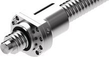
Arrestor nut
Certification
load errorDelivery notes
load errorSafety Instructions
load errorDownloads
 | Ball Screw Assemblies Manual | R320103992 | 2011-06-01 | English, French, German, Italian | PDF | 2MB Product Groups: Linear Screw Assemblies |
| Ball Screw Assemblies Manual | R320103993 | 2011-06-01 | English, German, Spanish, Portuguese | PDF | 2MB Product Groups: Linear Screw Assemblies only PDF |
| Catalog screw assemblies Catalog | R999001185 | 2021-04-01 | English | PDF | 30.7MB Product Groups: Ball Screw Assemblies, Planetary Screw Assemblies Only available as PDF - Ball screw assemblies BASA/Planetary screw assemblies PLSA |

Цена по запросу
Нет отзывов об этом товаре.